Direct current link circuit

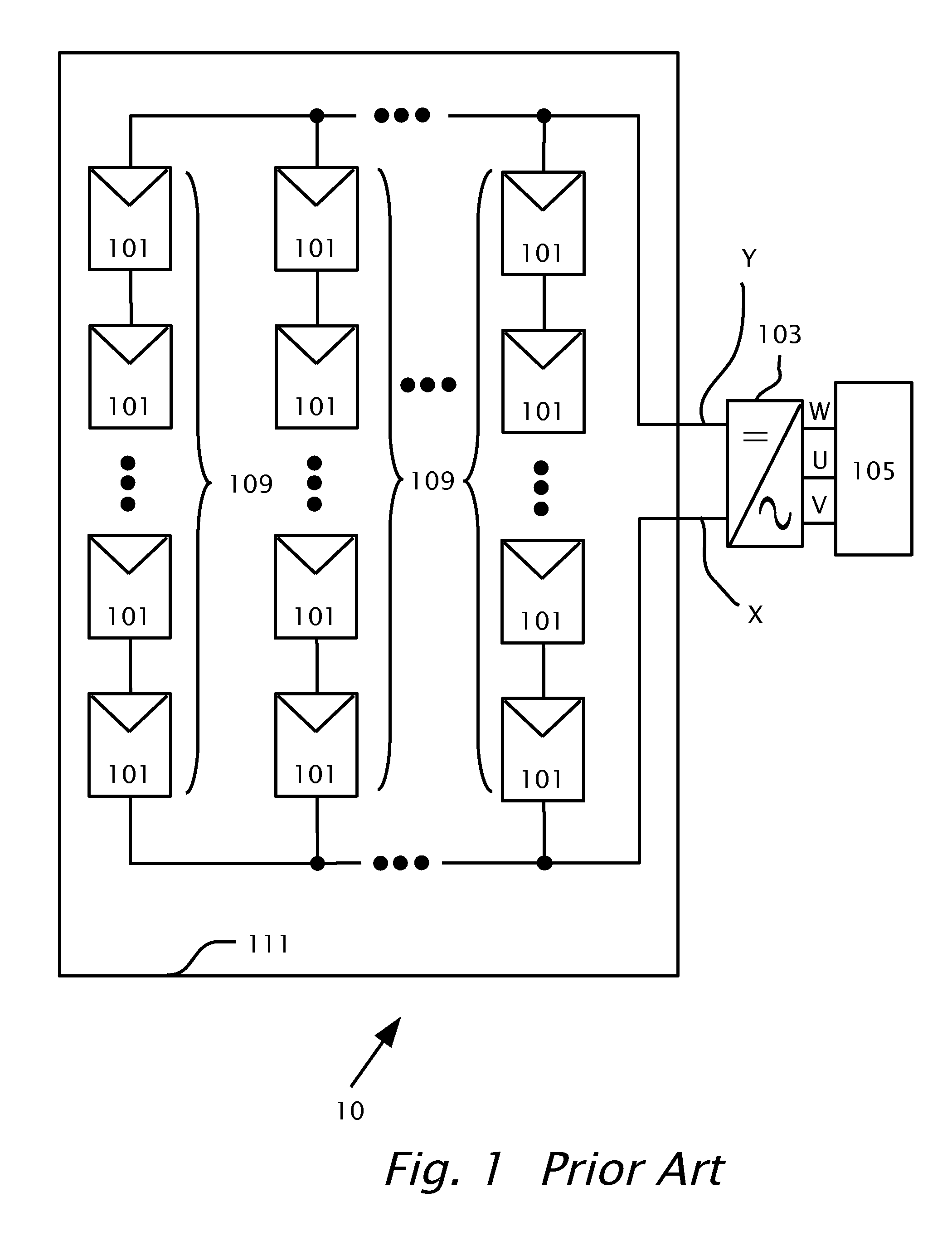
a direct current link circuit and direct current technology, applied in the direction of electric variable regulation, process and machine control, instruments, etc., can solve the problems of reducing the overall efficiency of conversion of dc power to three phase ac power, increasing the cost and complexity of additional boost or transformer isolation circuit, and causing problems such as the inability to meet the requirements of the input voltage over 600 volts,

Active Publication Date: 2013-03-14
SOLAREDGE TECH LTD
View PDF5 Cites 124 Cited by
  • Summary
  • Abstract
  • Description
  • Claims
  • Application Information

AI Technical Summary

Problems solved by technology

In North America, an input of voltage over 600 volts may create an issue with safety agency approval under regulation UL1741.
The additional boost or transformer-isolated circuit increases cost and complexity especially since the additional power converter module generally requires dedicated control and protection features.
Additionally, the boost or transformer-isolated circuit may also generate electromagnetic interference (EMI) and may cause reduction in overall efficiency of conversion of DC power to three phase AC power.

Method used


Image

  • Direct current link circuit
  • Direct current link circuit
  • Direct current link circuit

Examples


Embodiment Construction

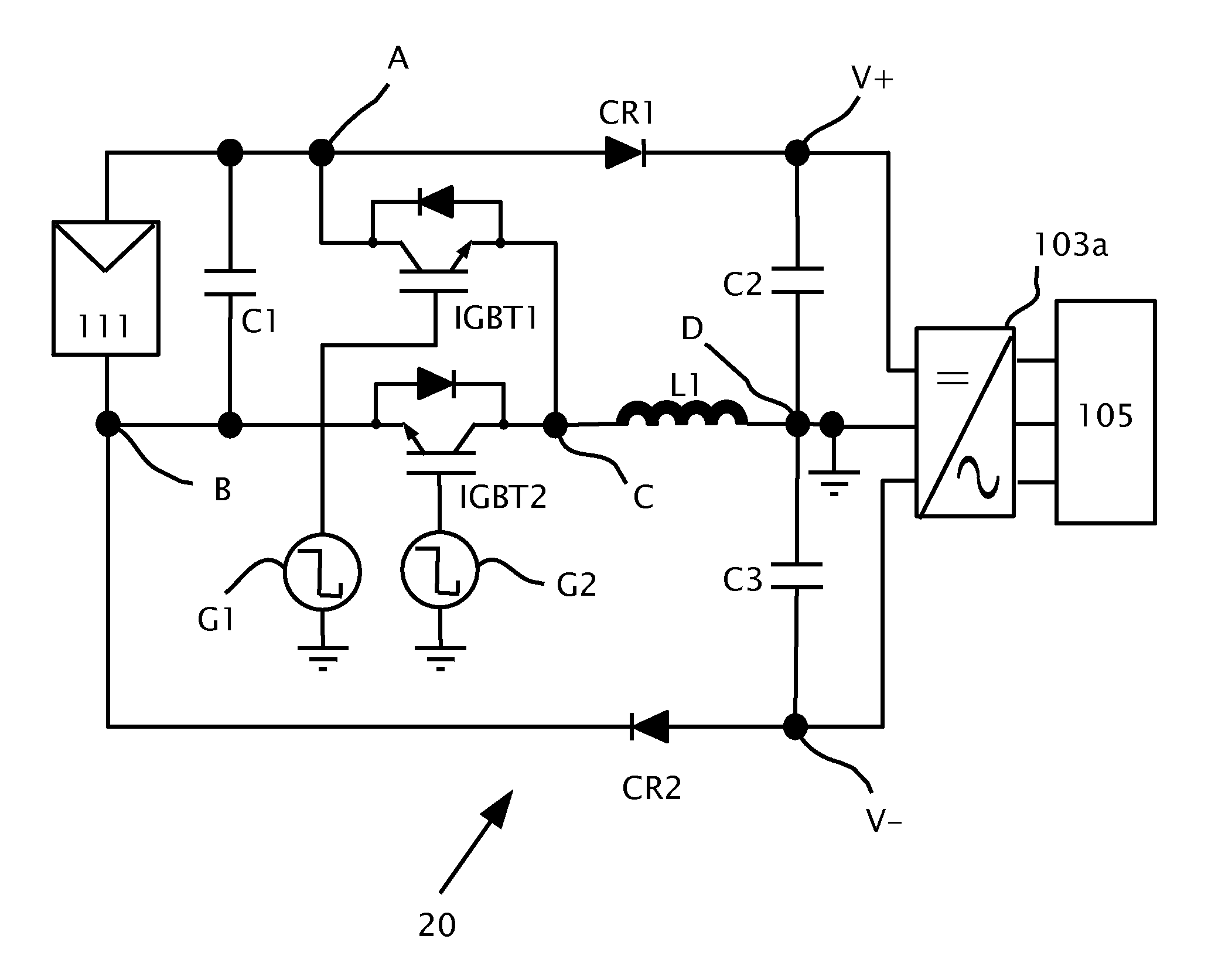
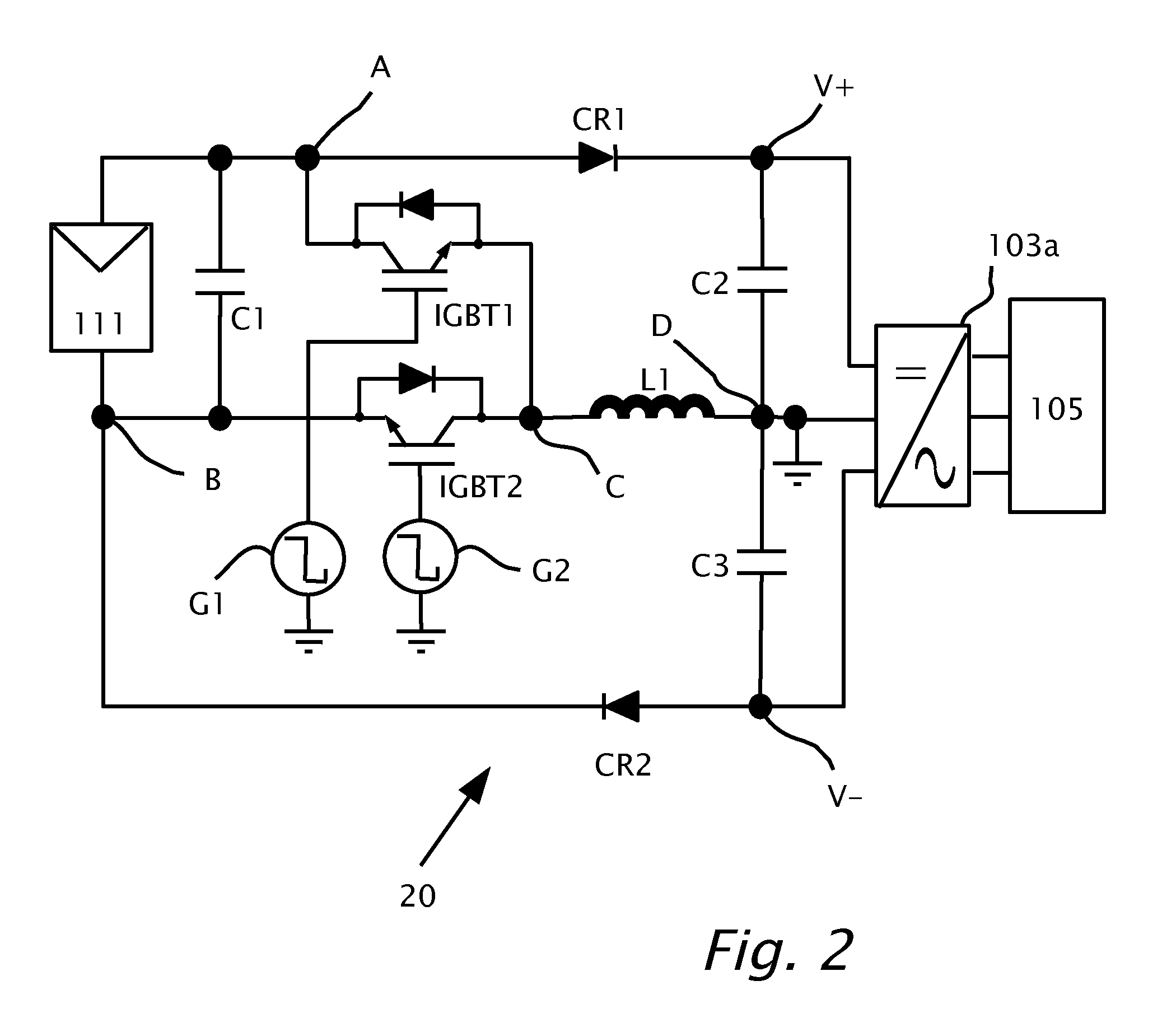
[0013]Reference will now be made in detail to features of the present invention, examples of which are illustrated in the accompanying figures. The features are described below to explain the present invention by referring to the figures.

[0014]Before explaining features of the invention in detail, it is to be understood that the invention is not limited in its application to the details of design and the arrangement of the components set forth in the following description or illustrated in the figures. The invention is capable of other features or of being practiced or carried out in various ways. Also, it is to be understood that the phraseology and terminology employed herein is for the purpose of description and should not be regarded as limiting. For example, the definite articles “a” and “an” used herein, such as in “a switch” and “a DC output” have the meaning of “one or more,” e.g., “one or more switches” and “one or more DC outputs.”

[0015]It should be noted, that although th...


PUM


Abstract

A device for converting power from a floating source of DC power to a dual direct current (DC) output, the device includes: positive and negative input terminals connectible to the floating source of DC power; and positive and negative, and ground output terminals connectible to the dual DC output that may feed an inverter. The inverter may be either a two or three level inverter. A charge storage device may be connected in parallel to, and charged from, the positive and negative input terminals. A resonant circuit may be also connected between the charge storage device and the dual DC output. The resonant circuit may include an inductor connected in series with a capacitor. The charge storage device may discharge through the resonant circuit by switching through to either the negative output terminal or the positive output terminal.

Description

TECHNICAL FIELD[0001]Aspects of this disclosure relate to distributed power systems, particularly a photovoltaic power harvesting system and, more particularly to a direct current link circuit connected between a photovoltaic array and a 3-phase inverter circuit.BACKGROUND[0002]In a conventional photovoltaic power harvesting system configured to feed a single phase or a three phase alternating current (AC) power grid, dual (positive and negative) direct current (DC) power may be generated first from solar panels. The three phase inverter powered by the dual (positive and negative) DC power produces three phase AC power at the output of the three phase inverter. Conventionally, sufficiently high DC voltage may be provided to the input of the three phase inverter by connecting solar panels in series. However, in order to increase overall power conversion efficiency, the sum of positive and negative DC rails required by the inverter may be over 600 volts.[0003]In North America, an inpu...

Claims


Application Information

Patent Timeline
Patent Type & Authority Applications(United States)
IPC IPC(8): G05F3/08
CPCH02J3/383H02M3/1563Y02E10/563H02J2300/10H02J2300/24H02J3/381Y02E10/56
Inventor LUBOMIRSKY, VADIM
Owner SOLAREDGE TECH LTD
Why Eureka
Try Eureka