Earth leakage detector with suffered current-blocking function

a technology function, which is applied in the field can solve the problems of earth leakage detector, such as the earth leakage relay, being subjected to so-called “suffered operation” and suffering operation, and achieve the effect of avoiding suffered operation and low risk

Active Publication Date: 2013-03-14
LIFETECHNOS
View PDF2 Cites 23 Cited by
  • Summary
  • Abstract
  • Description
  • Claims
  • Application Information

AI Technical Summary

Benefits of technology

[0011]According to the present invention, the dynamic sensitivity voltage value of the voltage-establishment-level detecting circuit is set to a voltage at which the suffered leakage current by the application of the circuit wire-to-ground voltage on the circuit wire-to-ground capacitance of the circuit to be monitored falls under becomes lower than the established dynamic sensitivity current value of the earth leakage detector, and the leakage alarm operation is stopped only when it can be confirmed that the circuit wire-to-ground voltage exceeds the dynamic sensitivity voltage value and that the direction of the leakage current judged from the phase of the circuit wire-to-ground voltage Vdb coincide with the phase of a suffered current due to a ground fault on the power side, which flows from the L-side of the detecting zero-phase current transformer toward the K-side, so that the leakage event in question does not come from a grounding fault in the monitored circuit. Thus, there is no influence on the usual leakage detection in a high-sensitivity operational area less than the established dynamic sensitivity voltage value, and the dynamic sensitivity current can be supersensitized so as to avoid an electric shock. Despite the so-supersensitized dynamic sensitivity current, as a matter of course, it is possible to avoid a suffered operation since the circuit wire-to-ground voltage is generated at the complete grounding by a spark grounding of the other circuit, such as a ground fault of the power side. In other words, the earth leakage detector of the invention does not obstruct the usual operation of a leakage breaker, a leakage relay or the like in its high-sensitivity operational area in a range where the circuit wire-to-ground voltage is less than the established dynamic sensitivity voltage value. Instead, the earth leakage detector of the invention is formed so as to stop the leakage cutoff operation or the leakage alarm operation since the output control circuit is activated for a “trip-locked” condition only when the phase of the leakage current is judged as the suffered operational condition in a “suffered-operation” potential area where the circuit wire-to-ground voltage exceeds the established dynamic sensitivity voltage value. Accordingly, the present invention is applicable to even a “high-sensitive” type shock-guard leakage breaker or a “high-sensitive” type leakage relay with a sense of security.
[0012]Even when the present earth leakage detector is used in a construction field having a variety of grounding methods mixed, such as a case that a resistance between a B-class grounding electrode and a D-class grounding electrode varies and another case that a resistance between grounding electrodes vanishes in the integrated grounding method of converging respective grounding electrodes for communization, the present earth leakage detector operates as a conventional leakage detector as long as a circuit wire-to-ground voltage does not occur. Therefore, it is possible to use the present earth leakage detector with a sense of security.
[0013]In an electric control system maintenance work etc. of productive facilities requiring a maintenance while causing no blackout, the utilization on prevention of electrification accidents could be greatly expected in a shock-guard and high-sensitivity leakage breaker with suffering-lock to which the present invention is applied.
[0014]In view of its usability, it is easy to incorporate such a shock-guard and high-sensitivity leakage breaker with suffering-lock on the application of the present invention into a construction because one has only to connect an earth terminal of the present leakage breaker with a D-class grounding or a ground structure of an electrical equipment. Even if this ground connection fails, the present leakage breaker has a low risk in undertaking the construction since it can serve as a conventional high-sensitivity leakage breaker.

Problems solved by technology

As a result, there is frequently-caused a phenomenon where earth leakage detectors, such as an earth leakage relay and an earth leakage breaker, are subjected to so-called “suffered operation”.
In addition, in even a load circuit where circuit respective phases' inter-grounding capacitances come to equilibrium causing respective leakage currents to be cancelled with each other invisibly, such as a single-phase three-wire system circuit and a star connection circuit, a circuit wire-to-ground voltage Vdb resulting from an earth fault leads to a flowing of a suffered current toward a resultant value of respective phases' wire-to-ground capacitances since the circuit inter-grounding voltage is a zero-phase voltage, causing a suffered operation.
Thus, as the ground resistance Rg comes close to 0Ω, the circuit wire-to-ground voltage Vdb grows to cause the likelihood of suffered operation to be increased.
Although the current countermeasure is to prevent an occurrence of suffered operation by setting a dynamic sensitivity current larger than a suffered current flowing by a maximum circuit wire-to-ground voltage generated by a ground fault, it becomes difficult to make a high-sensitivity operation required for an electrical shock prevention.
However, if this method is applied to a direct-grounding distribution type circuit undertaking a B-class grounding construction carelessly, it is supposed that it becomes difficult to ensure a stable zero-phase voltage in a situation where the resistance between grounding electrodes is increased / decreased or denied due to integrated grounding or the like.
After all, it is considered difficult to satisfy both of the prevention of a suffered operation and the high-sensitivity operation for electrical shock prevention.

Method used


Image

  • Earth leakage detector with suffered current-blocking function
  • Earth leakage detector with suffered current-blocking function
  • Earth leakage detector with suffered current-blocking function

Examples


embodiment 1

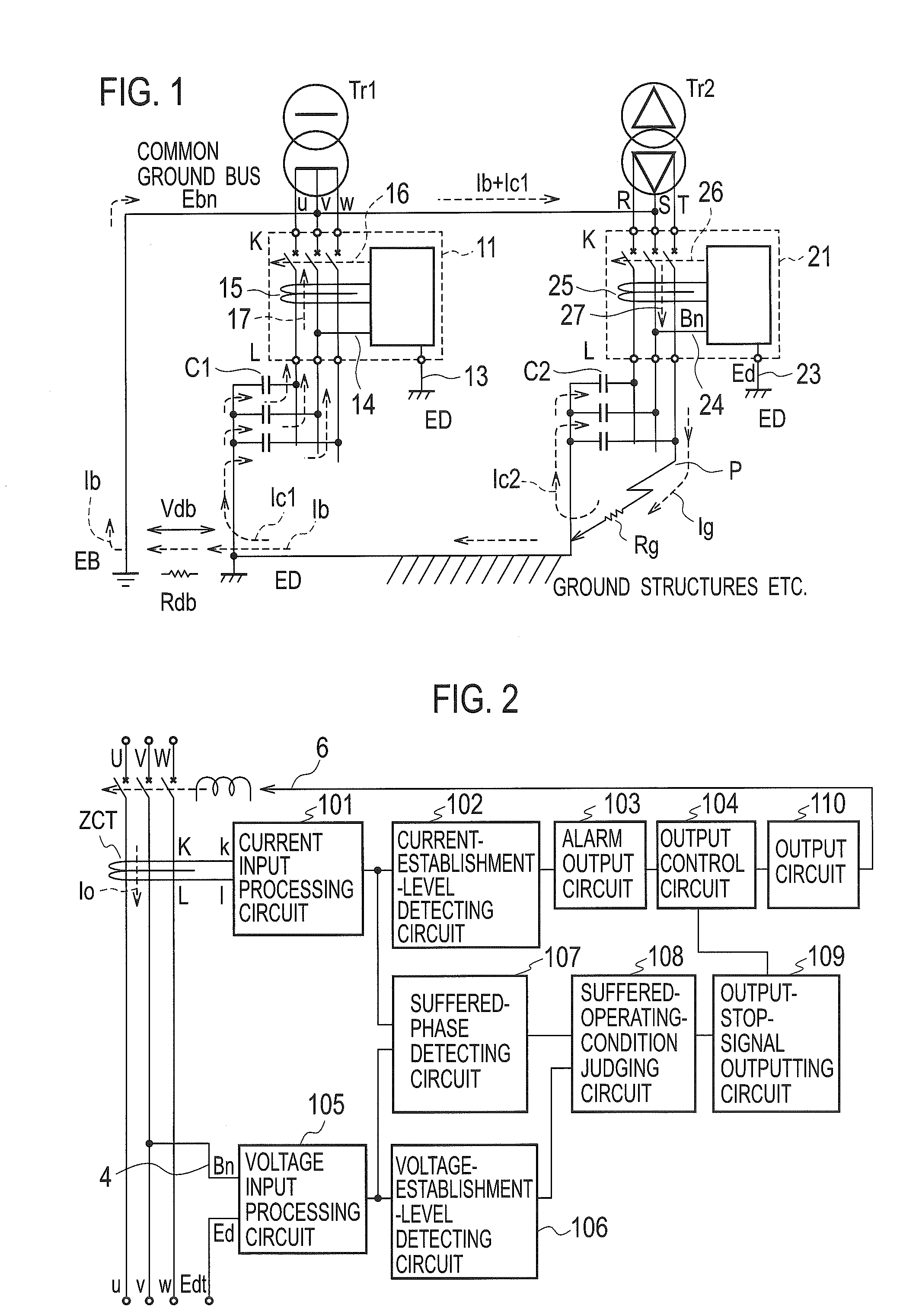
[0025]FIG. 1 shows an embodiment that earth leakage breakers 11, 21 with suffering-lock of the present invention are installed in a standard substation where both a neutral phase v of a single-phase three-wire system electric light transformer Tr1 and an end S phase of a three-phase three-wire power transformer Tr2 are collectively connected to a common ground bus Ebn for B-class grounding and further connected to a grounding electrode EB of a B-class grounding construction. The earth leakage breaker 11 has the same performance as that of the earth leakage breaker 21. Referring to FIG. 1, we now describe the operation at a grounding fault that a T-phase of the power transformer Tr2 is connected to ground through a ground-fault resistance Rg at a point P. Through the intermediary of D-class grounding electrodes ED or ground structures connected to these electrodes ED, the ground-fault current Ig produced through the ground-fault resistance Rg is divided into a current Ic2 returning t...

embodiment 2

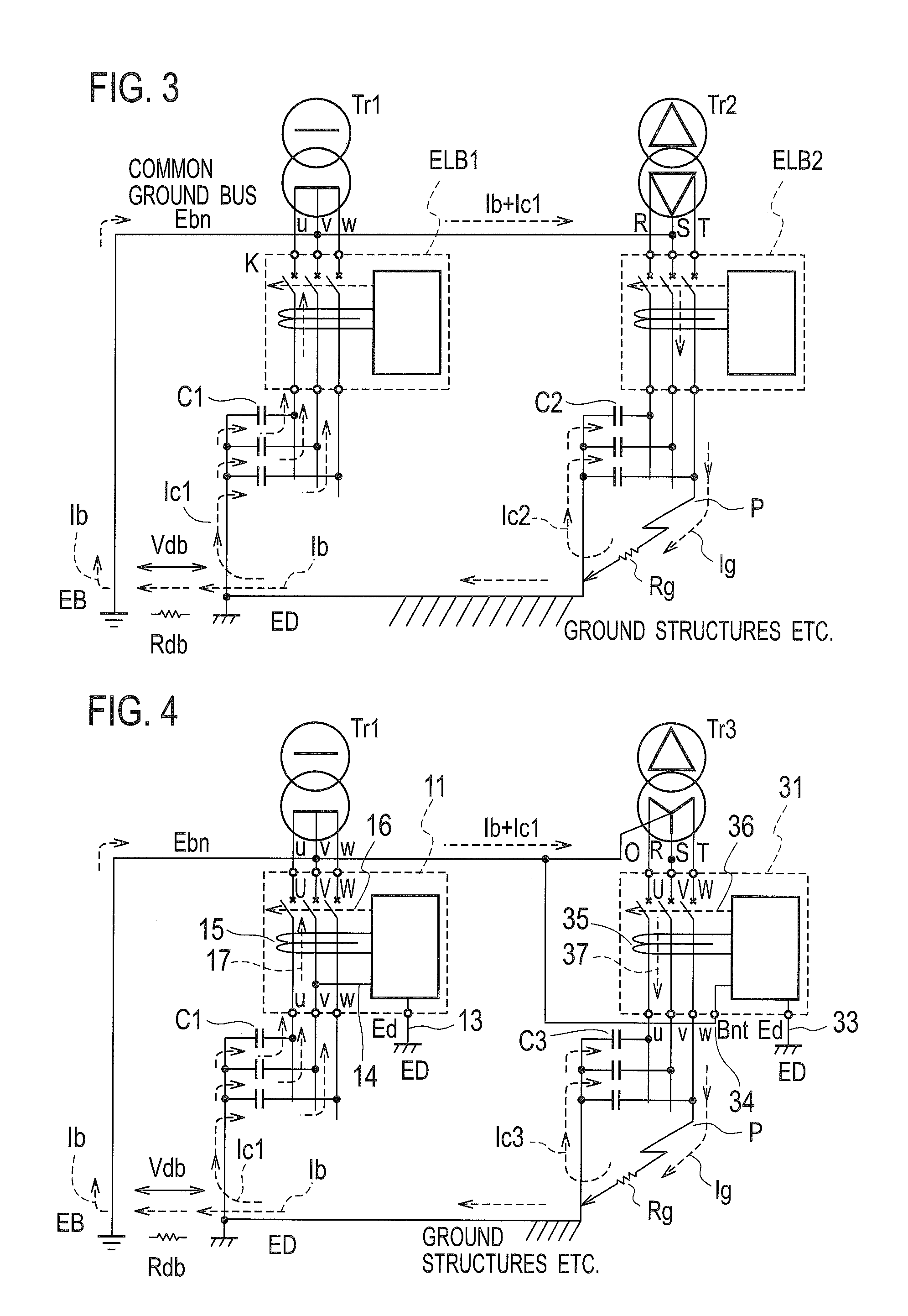
[0033]FIG. 4 showing an embodiment that the earth leakage breakers 11 and 31 with suffering-lock of the present invention are installed in a substation where both the neutral phase v of the single-phase three-wire system electric light transformer Tr1 and a neutral point terminal O of a three-phase three-wire Y-connection type power transformer Tr3 are collectively connected to the common ground bus Ebn for B-class grounding and further connected to the grounding electrode EB of the B-class grounding construction. The earth leakage breaker 31 with suffering-lock is provided, for the three-phase three-wire Y-connection type power transformer, with a B-class grounding electrode connecting terminal Bnt as an independent terminal. This terminal is connected to the neutral terminal O of the Y-connection type power transformer through a connecting wire 34. The embodiment 2 is similar to the embodiment 1 with respect to the flow of a suffered current by a ground fault at the point P and th...

embodiment 3

[0035]FIG. 6 showing an embodiment that the earth leakage breakers 11 and 41 with suffering-lock of the present invention are installed in a substation where both the neutral phase v of the single-phase three-wire system electric light transformer Tr1 and a neutral point terminal O of a three-phase four-wire Y-connection type power transformer Tr4 are collectively connected to the common ground bus Ebn for B-class grounding and further connected to the grounding electrode EB of the B-class grounding construction. For a three-phase four-wire Y-connection type power transformer, the earth leakage breaker 41 with suffering-lock includes a main circuit for four wires and a B-class grounding electrode connecting terminal Bnt as an independent terminal, constituting the earth leakage breaker with suffering-lock of the present invention. This terminal is connected to the neutral terminal O of the Y-connection type power transformer through a connecting wire 44. The embodiment 3 is similar ...


PUM


Abstract

A leakage detector is provided with the addition of an output control circuit that monitors a circuit wire-to-ground voltage, which is at the root of a suffered operation and produced between a transformer B-class grounding phase of a monitored circuit and a D or C-class grounding electrode or a ground structure etc. of an electrical equipment connected to the grounding electrode, execute a phase judgment of a leakage current detected by a zero-phase current transformer on the basis of the monitored voltage, and stop an output operation of the leakage detector when the leakage current is a suffered current flowing from a load side L of the detecting zero-phase current transformer toward the power side K, i.e. the transformer and when the circuit wire-to-ground voltage exceeds an appropriately-established dynamic sensitivity voltage value.

Description

CROSS REFERENCE TO RELATED APPLICATIONS[0001]This is a U.S. national stage of application No. PCT / JP2011 / 060019, filed on 25 Apr. 2011. Priority under 35 U.S.C. §119(a) and 35 U.S.C. §365(b) is claimed from Japanese Application No. 2010-118544, filed 24 May 2010, the disclosure of which are also incorporated herein by reference.TECHNICAL FIELD[0002]The present invention relates to an earth leakage detector, such as an earth leakage relay and an earth leakage breaker, for ensuring safety and security of electricity.BACKGROUND ARTS[0003]An earth leakage detector, such as an earth leakage breaker and an earth leakage relay for electric shock prevention, which has been developed for the purpose of preventing electrification fatal and injury accident with mobile-portable electric machinery and appliance in accordance with occupational safety and health regulations, has become popular for its low cost and ease of use. For this reason, this earth leakage detector has been also in heavy usa...

Claims


Application Information

Patent Timeline
Patent Type & Authority Applications(United States)
IPC IPC(8): G01R31/02H02H3/16
CPCH02H3/347G01R31/025G01R31/52H01H83/02H02H3/38H02H7/26
Inventor KATAOKA, KOHZOH
Owner LIFETECHNOS
Why Eureka
Try Eureka