Ultrasound transducer for selectively generating ultrasound waves and heat

Active Publication Date: 2013-03-14
KONINKLIJKE PHILIPS ELECTRONICS NV
View PDF15 Cites 6 Cited by
  • Summary
  • Abstract
  • Description
  • Claims
  • Application Information

AI Technical Summary

Benefits of technology

[0007]Hence, it is an object of the invention to provide heating means for an ultrasonic app

Problems solved by technology

However, it may not always be advantageous to use the exac

Method used


Image

  • Ultrasound transducer for selectively generating ultrasound waves and heat
  • Ultrasound transducer for selectively generating ultrasound waves and heat
  • Ultrasound transducer for selectively generating ultrasound waves and heat

Examples


Example

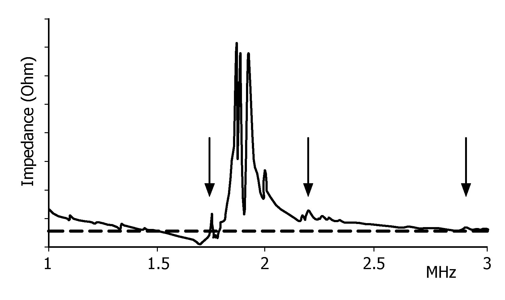
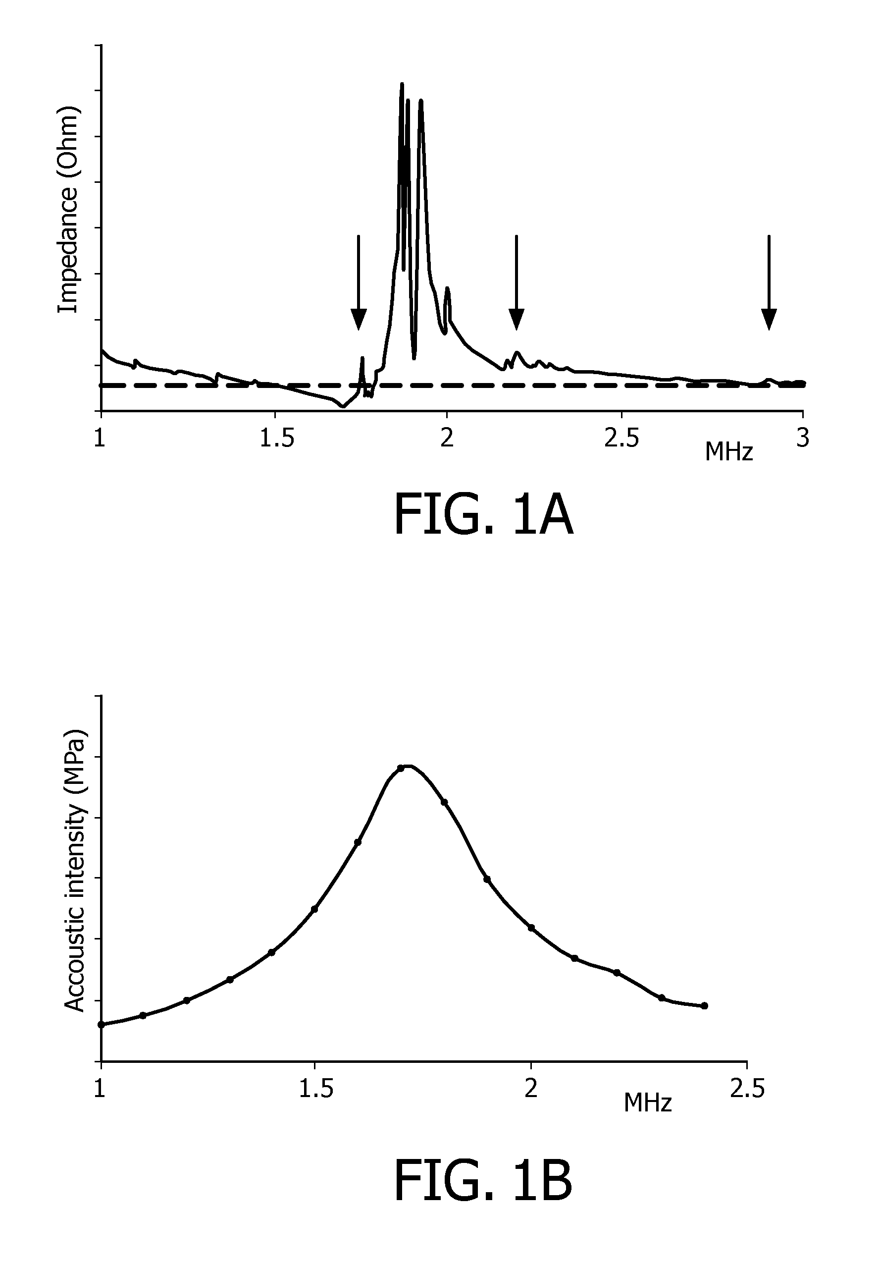
[0020]For enabling heating as well as treating with ultrasound, an ultrasound transducer is used that can be driven at at least two different frequencies. One of these frequencies should be adapted for the efficient generation of ultrasonic waves, whereas the other frequency should result in heating up the ultrasound transducer, almost without generation of ultrasonic waves. Various types of ultrasonic transducers may be employed, such as piezoelectric ultrasound transducers or capacitive micro-machined ultrasound transducers. Preferably, high intensity focused ultrasound transducers (HIFU-transducers) are employed that are able to focus the ultrasonic beam to a small focal region in a sample. It is also preferred to use resonance frequencies for driving the ultrasound transducer, in order to ensure a favorable transformation ratio of input electrical energy to output energy. However, in some cases, it may be preferable to use frequencies close to a resonance frequency, multitudes o...


PUM


Abstract

In order to provide heating means for an ultrasonic application setup, adapted for heating a sample (20) gently and fast and saving costs and space, an ultrasound transducer (10) capable of being driven at multiple frequencies including a main frequency for efficient production of ultrasound waves and at least one alternative frequency, at which almost no ultrasound is generated, a system for sample analysis comprising such an ultrasound transducer (10) and a method for controlling such an ultrasound transducer (10) are proposed, wherein the ultrasound transducer (10) is driven either at the main frequency for generating ultrasonic waves or at the alternative frequency for generating heat in the ultrasound transducer (10), if the sample (20) is to be heated.

Description

FIELD OF THE INVENTION[0001]The invention relates to the field of ultrasound transducers, and in particular to ultrasound transducers for selectively generating ultrasound waves and heat for use in analysis and / or diagnostics.BACKGROUND OF THE INVENTION[0002]Since long, ultrasound is used in the field of medical treatment. Recently, ultrasonic transducers, in particular high intensity focused ultrasound transducers, have been used for inducing lesions in tissue for therapeutic cancer treatment. Tissue lesion or tissue destruction is caused by cavitation effects of high intensity ultrasonic waves. This cavitation effect is linked to the formation of microscopic vapor bubbles in a region, where the pressure of liquid falls below its vapor pressure. When these bubbles collapse, energy is released leading to the destruction of neighboring tissue.[0003]U.S. Pat. No. 5,601,526 describes a method and an apparatus for performing therapy using ultrasound for tissue disruption by means of cav...

Claims


Application Information

Patent Timeline
IPC IPC(8): A61N7/02G01N29/34
CPCA61B8/00A61N7/02G01N29/34A61N2007/0073A61N7/022A61N2007/0039G01N29/2431G01N2291/02881G01N29/348G01N2291/101
Inventor VAN HEESCH, CHRISTIANUS MARTINUSKOLESNYCHENKO, ALEKSEY
Owner KONINKLIJKE PHILIPS ELECTRONICS NV
Why Eureka
Try Eureka