
Drop catcher

a technology of drop catcher and drop catcher, which is applied in the field of nucleic acid isolation and amplification, can solve the problems of not receiving and incorporating liquid escape, active movement of drop catcher, and not mechanically coupling of drip tray, so as to reduce the need, reduce the complexity, and save space and cost.

Active Publication Date: 2010-10-26
ROCHE MOLECULAR SYST INC
View PDF13 Cites 0 Cited by
  • Summary
  • Abstract
  • Description
  • Claims
  • Application Information

AI Technical Summary

Benefits of technology

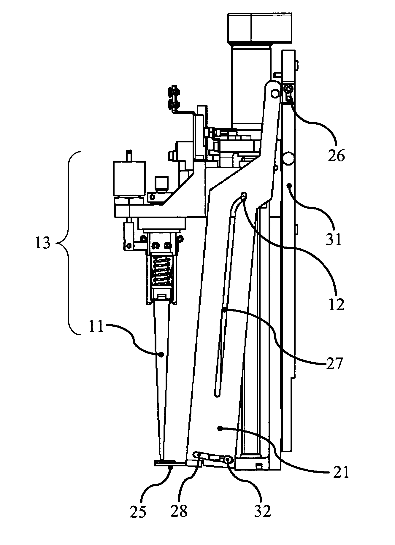
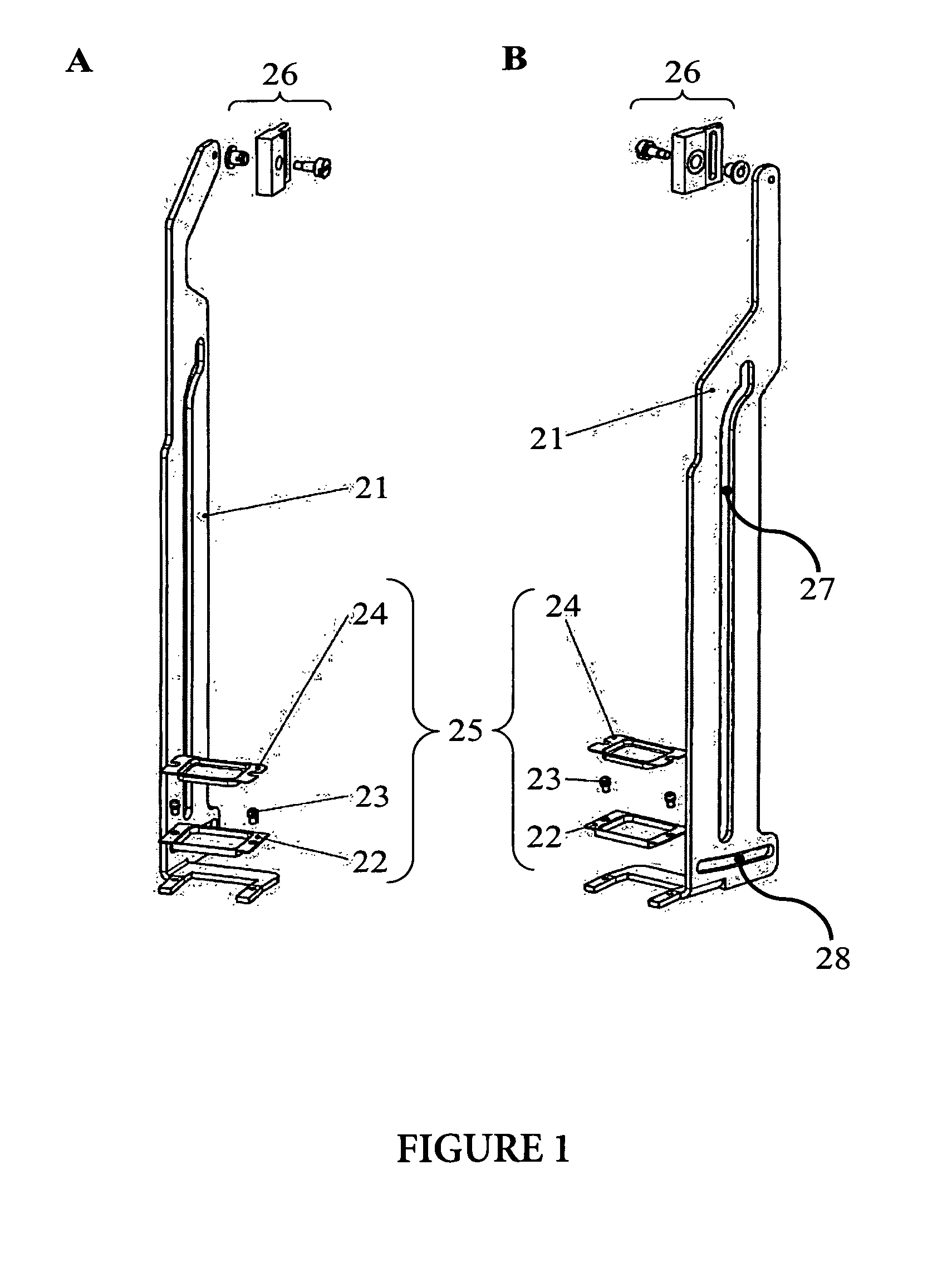
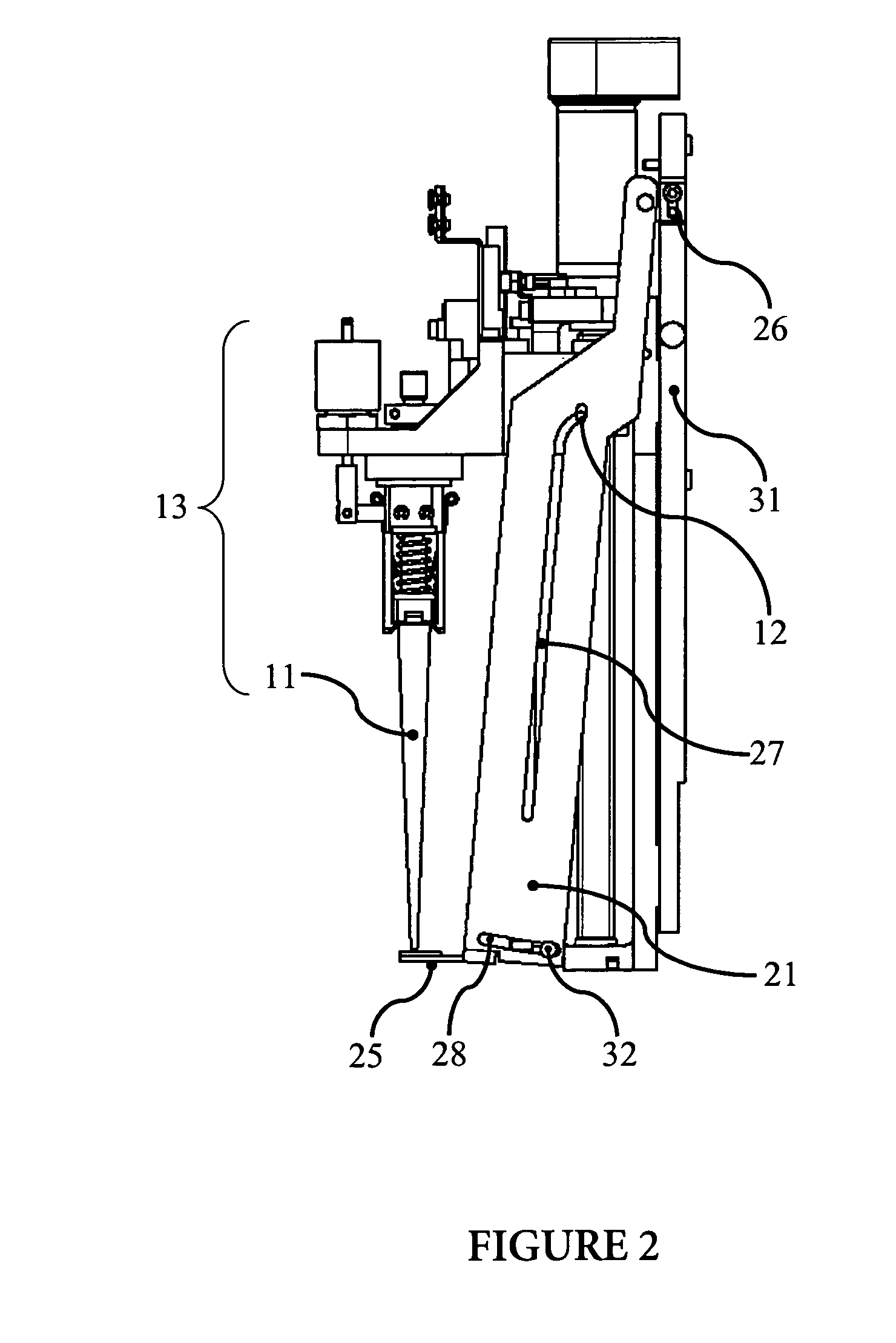
[0027]An advantage of the invention is that due to the mechanical coupling of the movement of the device for catching drops to the movement of the pipetting device there is no necessity for the installation of a second actuator in order to move the device for catching drops to a position below the opening of said pipetting device, which is very space-and cost-saving. Furthermore, in fully automated analytical instruments this leads to reduced complexity and decreased necessity to monitor the reliability of the movement of the device for catching drops via sensors as both, the movement of the pipetting device and the movement of the device for catching drops can be monitored with only one sensor. Thus, the invention contributes to a simplified composition of the analytical instrument without the need for a second sensor for monitoring the movement of the second actuator. One sensor and one actuator are capable of controlling two different but coupled functions (movement of the pipetting device and movement of the device for catching drops).
[0028]A further advantage of the invention is that each pipetting device mounted on a pipetting head is coupled to one device for catching drops. Therefore, it is possible to operate each pipetting device independently from the other pipetting device or devices without increasing the potentiality of contamination of the instrument. The pipetting head is moved in such a way that one pipetting device is located at the desired position to perform the pipetting procedure. The movement of the pipetting device leads to the movement of the one device for catching drops positioned underneath its opening. Thereby, the opening of said pipetting device is unshielded and liquid may be dispensed from the pipetting device to the vessel. At the end of the pipetting procedure the pipetting device is moved again thereby re-shielding the opening of said pipetting device and permitting the device for catching drops to receive and incorporate liquids emerging from the pipetting device after the end of the pipetting procedure. During the pipetting procedure the openings of the other pipetting devices mounted on the pipetting head are still covered. Thus, this construction minimizes the potentiality of contamination during the pipetting procedures and the movement of the pipetting head.

Problems solved by technology

Furthermore, the movement of the drip tray is not mechanically coupled to the vertical movement of the syringe.
This embodiment has the disadvantage that the opening of the pipette assembly is not covered by the contamination guard when the pipette assembly is moved and therefore, may not receive and incorporate liquids escaping from the opening of the pipette assembly or dripping from the outer walls of the pipette assembly when the pipette assembly is withdrawn from the multi-chamber assembly.
For integrated systems drop catchers as used in the MagNA Pure Compact, the MagNA PureLC instruments or as disclosed in EP 1110609 and EP 1508809 have the common disadvantage that an active movement of the drop catcher is performed by a second actuator independent of the movement of the pipetting device, which is conducted by a first actuator.
However, the integration of a second actuator on a pipetting head is very space consuming and also very costly.
Furthermore, a drop catcher as described before is not useful, when more than one pipetting device is mounted on a pipetting head and when these pipetting devices shall operate independently from another without increasing the potentiality of contamination of the instrument.

Method used


Image

  • Drop catcher
  • Drop catcher
  • Drop catcher

Examples


Embodiment Construction

[0037]As used herein, the term analytical instrument refers to an instrument capable of the automated handling and processing of samples. In certain embodiments the analytical instrument may be used for the fully automated performance of sample preparation and / or nucleic acid amplification and / or detection of amplificates.

[0038]In this connection a pipetting device comprises an integrally built pipetting module which has an inlet / outlet which may be connected to a removable pipetting tip or integrally built with a pipetting tip and can be used for aspirating or dispensing liquids. During the pipetting procedure liquid will be aspirated to or dispensed from the pipetting tip. In another embodiment the pipetting tip may be a disposable made up from one or more plastic materials (e.g. polyethylene, polypropylene). In another embodiment the pipetting tip may be a needle or a steel needle.

[0039]In certain embodiments the pipetting device is considered to be part of the analytical instrum...


PUM


Abstract

The invention relates to a device for catching drops from a pipette mechanically attached to a pipetting device in the field of nucleic acid purification and amplification. Furthermore, a method for pipetting a liquid with a decreased potentiality of contamination of an analytical instrument as well as liquids or / and samples placed on said analytical instrument is provided. Moreover, an analytical instrument at least comprising a pipetting device, and a device for catching drops from a pipette mechanically attached to said pipetting device wherein the movement of the device for catching drops is coupled to the movement of said pipetting device is illustrated.

Description

BACKGROUND OF THE INVENTION[0001]This application claims the benefit of priority under 35 U.S.C. §119 of EP Application 05110647.4 filed Nov. 11, 2005, the contents of which are hereby incorporated by reference.[0002]1 . Field of the Invention[0003]The present invention is directed to instruments, devices and methods for use in the fields of nucleic acid isolation and amplification.[0004]2 . Description of Related Art[0005]Devices for catching drops for various applications are known in the art. WO200071330 describes a semi-automated lamination process and apparatus for laminating spherical and cylinder power ophthalmic lens blanks in a properly oriented alignment of the lens blanks. Herein, the apparatus may comprise a drip tray with a removable insert for catching a hardenable liquid adhesive from a syringe, which is located on the carriage underneath the syringe applicator at a distinct operating position. In particular, the drip tray is actively transported underneath the syring...

Claims


Application Information

Patent Timeline
Patent Type & Authority Patents(United States)
IPC IPC(8): B01L3/00
CPCB01L3/021G01N1/18G01N35/10B01L2200/0615G01N2035/102
Inventor BAUMANN, RENATOBERNET, ROLANDKERBLER, HEINZSCHORNO, RETO
Owner ROCHE MOLECULAR SYST INC
Learn More