Fieldbus device control system

Inactive Publication Date: 2013-03-14
GENERAL ELECTRIC CO
View PDF27 Cites 10 Cited by
  • Summary
  • Abstract
  • Description
  • Claims
  • Application Information

AI Technical Summary

Problems solved by technology

Changing the firmware in the controller each time the CANopen configuration or the

Method used


Image

  • Fieldbus device control system
  • Fieldbus device control system
  • Fieldbus device control system

Examples


Embodiment Construction

[0012]As used herein the terms module and sub-module refer to an application specific integrated circuit (ASIC), an electronic circuit, a processor (shared, dedicated, or group) and memory that executes one or more software or firmware programs, a combinational logic circuit, and / or other suitable components that provide the described functionality.

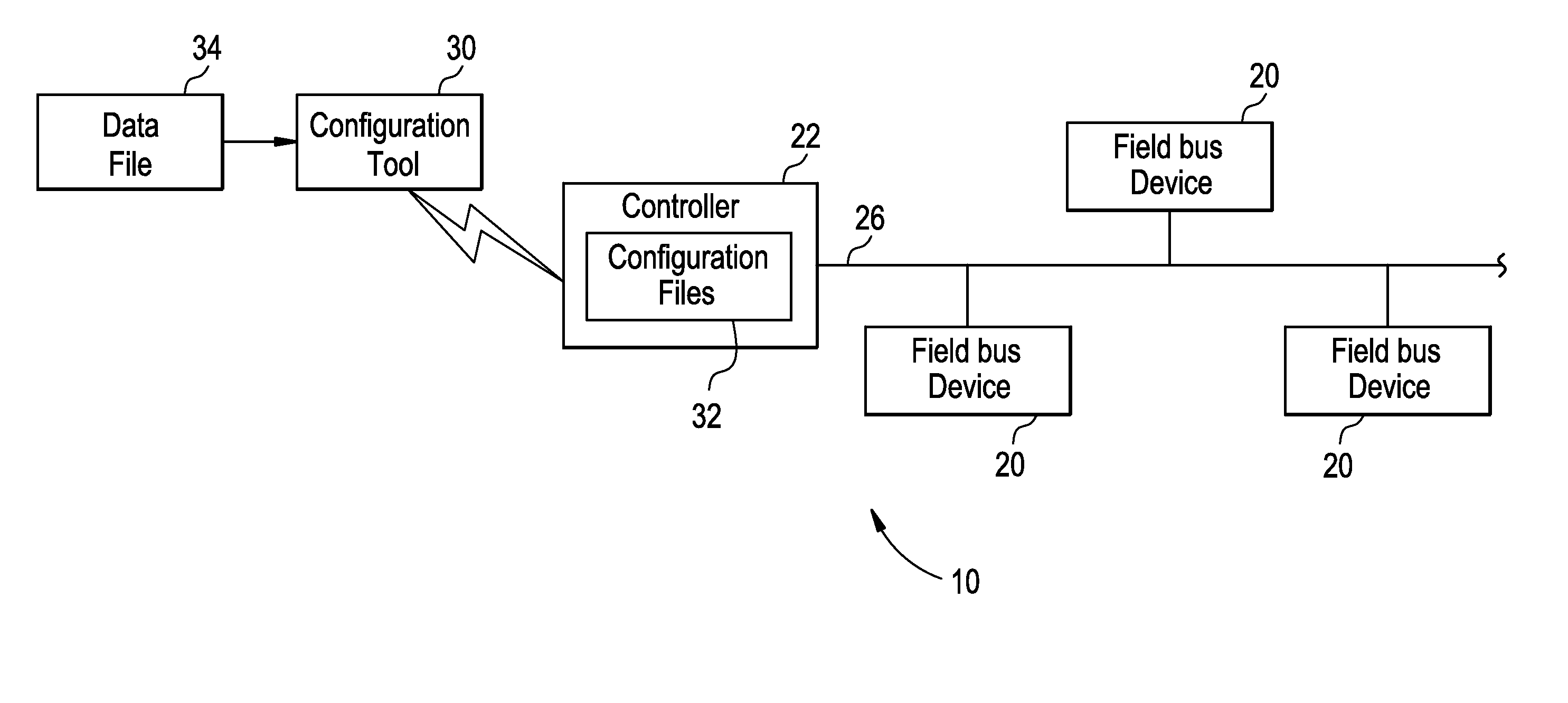
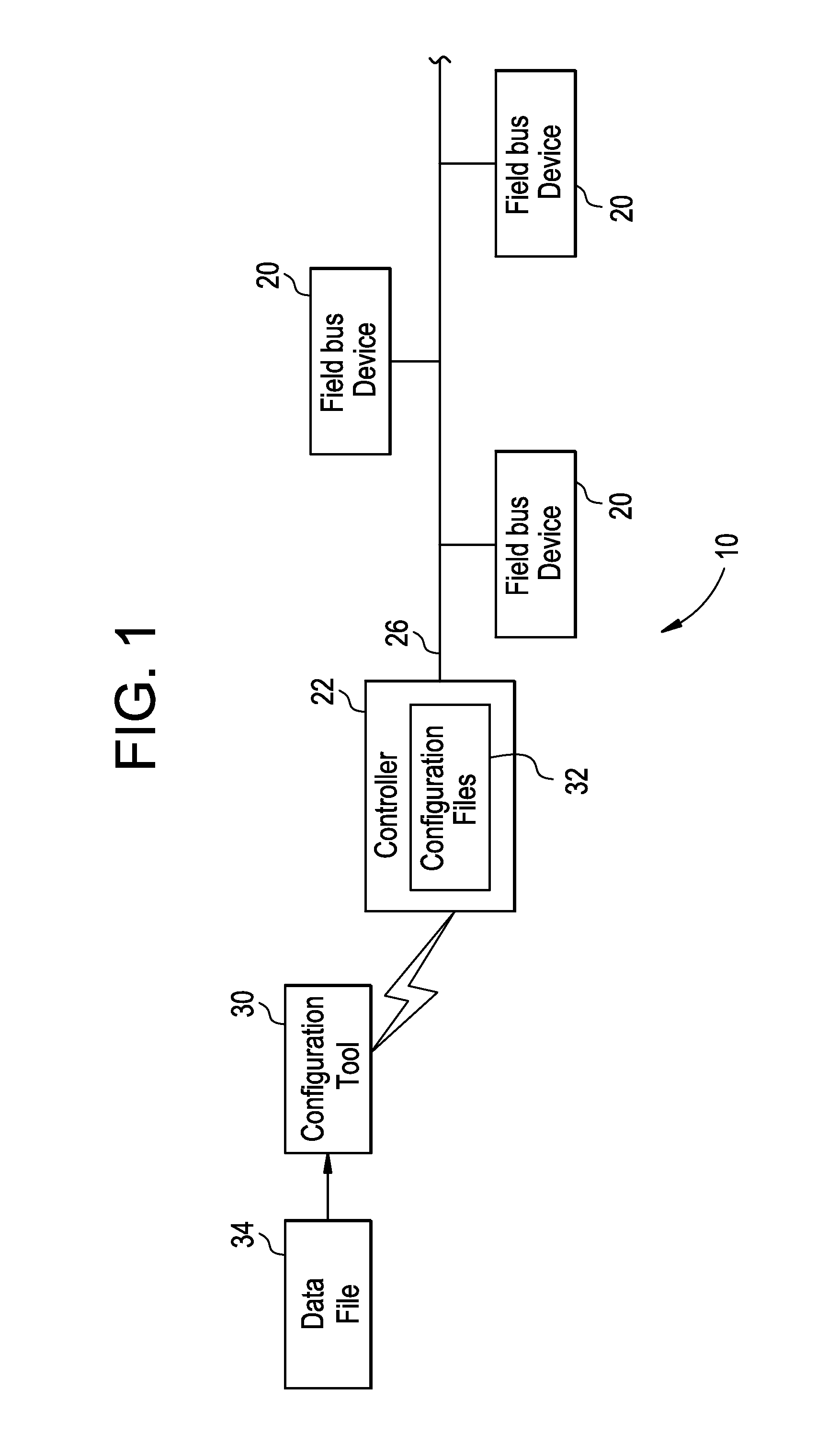
[0013]Referring now to FIG. 1, an exemplary schematic fieldbus system 10 is illustrated. The fieldbus system 10 includes a plurality of fieldbus devices 20 and a controller 22. The controller 22 is in communication with each of the fieldbus devices 20 through a fieldbus 26. The fieldbus system 10 utilizes a CANopen transfer data protocol to exchange messages between the controller 22 and the fieldbus devices 20. In one exemplary embodiment, the fieldbus system 10 may be used in conjunction with a gas turbine (not shown), where the fieldbus devices 20 are fuel valves for the gas turbine. However, it is understood that the fieldbus system 1...


PUM


Abstract

A fieldbus system is provided, having a plurality of fieldbus devices and a controller. The controller is in communication with the plurality of fieldbus devices though a fieldbus. The controller transmits a plurality of high priority Receive Process Data Objects (RPDOs) and a plurality of low priority RPDOs to the plurality of fieldbus devices through the fieldbus. The controller includes a control logic for sending each of the plurality of fieldbus devices one of the plurality of high priority RPDOs during a frame. The frame is the fastest rate at which the high priority RPDOs are transmitted. The controller includes a control logic for sending at least one of the plurality of fieldbus devices at least one of the plurality of low priority RPDOs. The low priority RPDOs are grouped by a minimum wait time.

Description

BACKGROUND OF THE INVENTION[0001]The subject matter disclosed herein relates to a fieldbus system, and more specifically to a fieldbus system having a controller transmitting a plurality of high priority Receive Process Data Objects (RPDOs) and low priority RPDOs to a plurality of fieldbus devices.[0002]A fieldbus is employed to monitor and control one or more pieces of production equipment such as, for example, sensors, actuators, electrical motors, or valves. A fieldbus is generally the equivalent of a local area network (LAN) type connection that requires only one communication point at a controller and allows for multiple pieces of production equipment to be connected concurrently. In one example, a transfer data protocol such as, for example, CANopen may be used to allow communication between the controller and the production equipment. Process data objects (PDOs) are used for broadcasting control and status information between the controller and the production equipment. Speci...

Claims


Application Information

Patent Timeline
IPC IPC(8): G05B11/01
CPCG05B19/0423G05B2219/25014H04L12/40039G05B2219/25032
Inventor KERR, III, FRANK LEONMATZKO, GEORGE ANDREW
Owner GENERAL ELECTRIC CO
Why Eureka
Try Eureka