Arc welding control method and arc welding apparatus

a control method and control method technology, applied in the direction of welding/cutting media/materials, welding apparatus, manufacturing tools, etc., can solve the problem of difficult operation of a conventional arc welding control method, and achieve the effect of reducing the energy input amount of a base metal

Active Publication Date: 2013-03-21
PANASONIC INTELLECTUAL PROPERTY MANAGEMENT CO LTD
View PDF2 Cites 38 Cited by
  • Summary
  • Abstract
  • Description
  • Claims
  • Application Information

AI Technical Summary

Benefits of technology

[0011]By the structure, an energy input amount to a base metal is reduced. Consequently, it is possible to weld a thin plate having a thickness of 0.6 mm or less without causing burn-through, for example, which is hard to perform by a conventional arc welding apparatus.

Problems solved by technology

Consequently, it is possible to weld a thin plate having a thickness of 0.6 mm or less without causing burn-through, for example, which is hard to perform by a conventional arc welding control method.

Method used


Image

  • Arc welding control method and arc welding apparatus
  • Arc welding control method and arc welding apparatus
  • Arc welding control method and arc welding apparatus

Examples


first exemplary embodiment

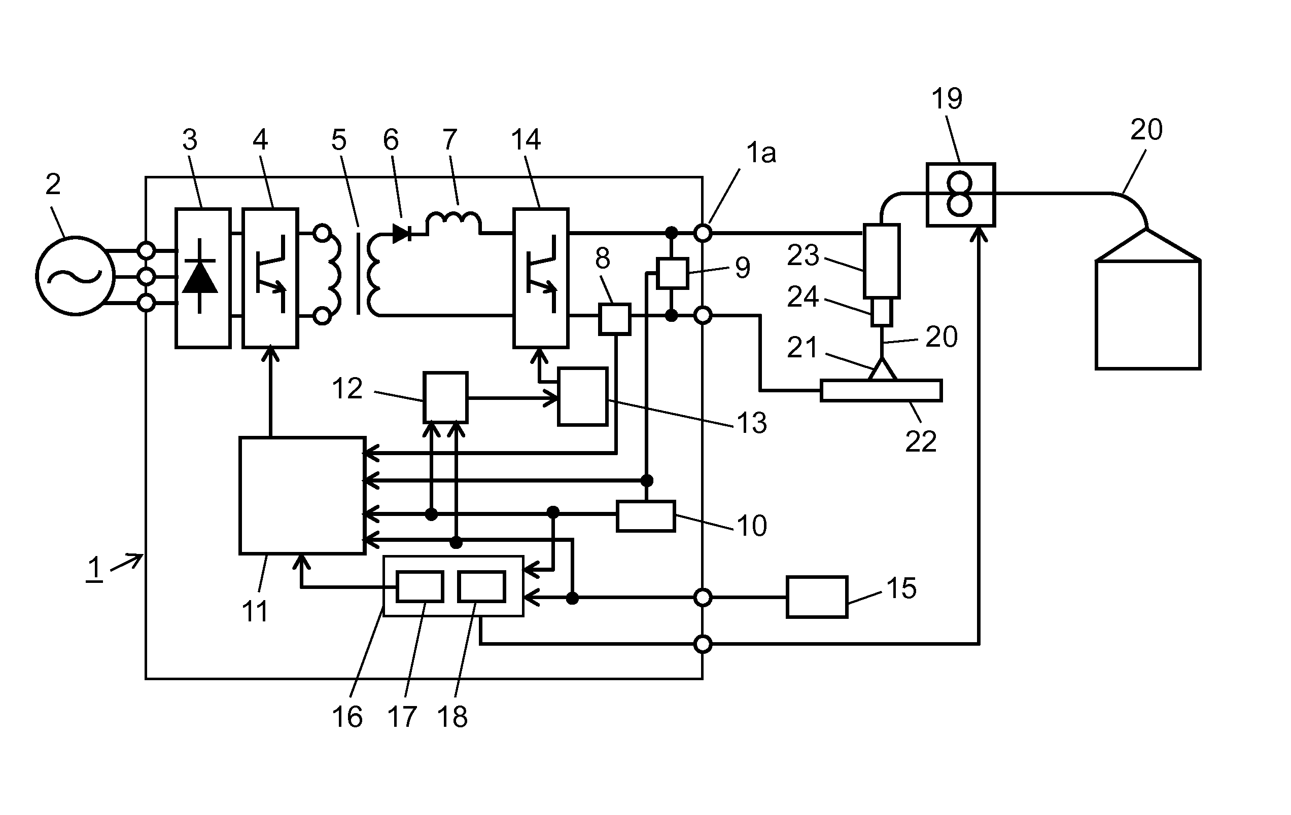
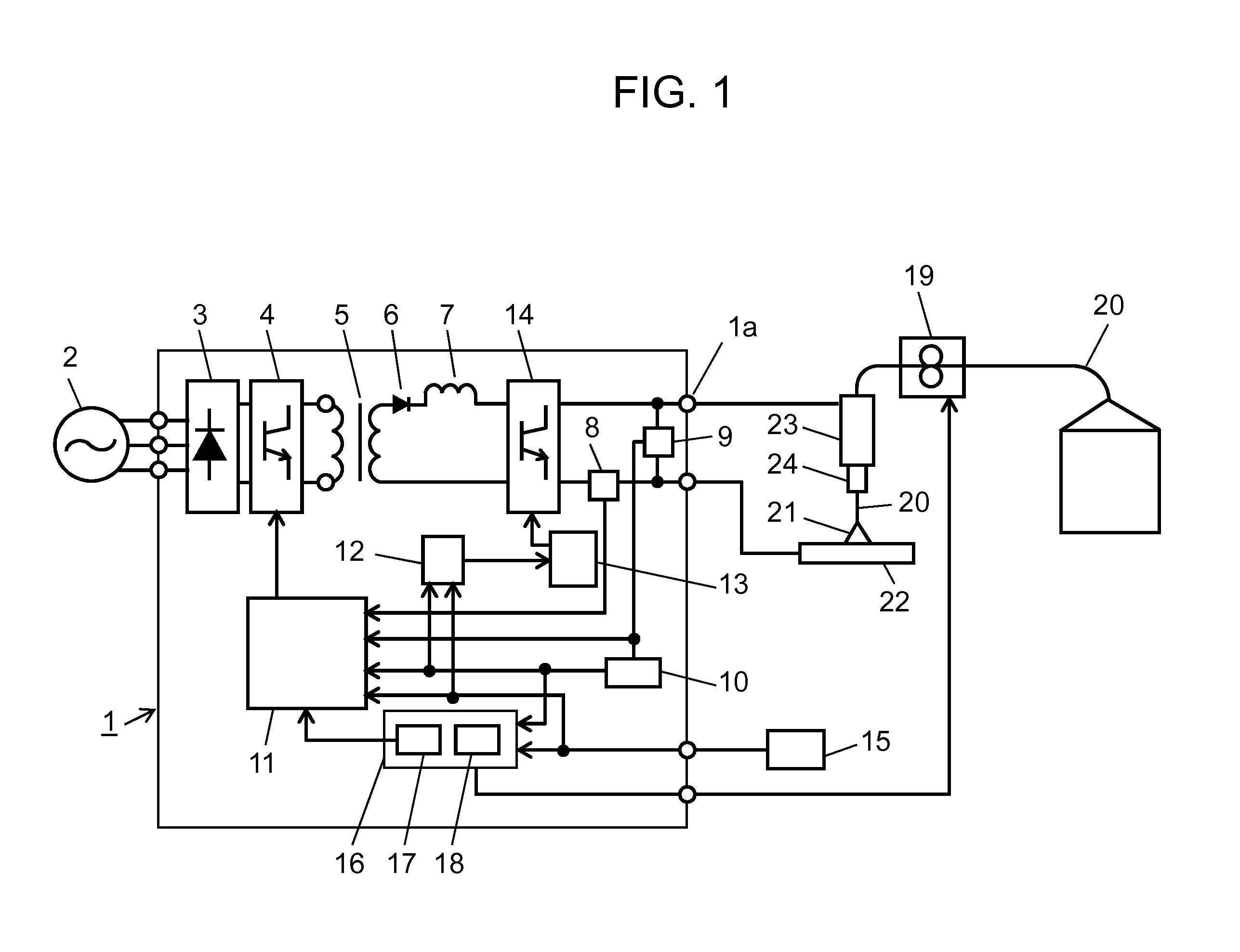
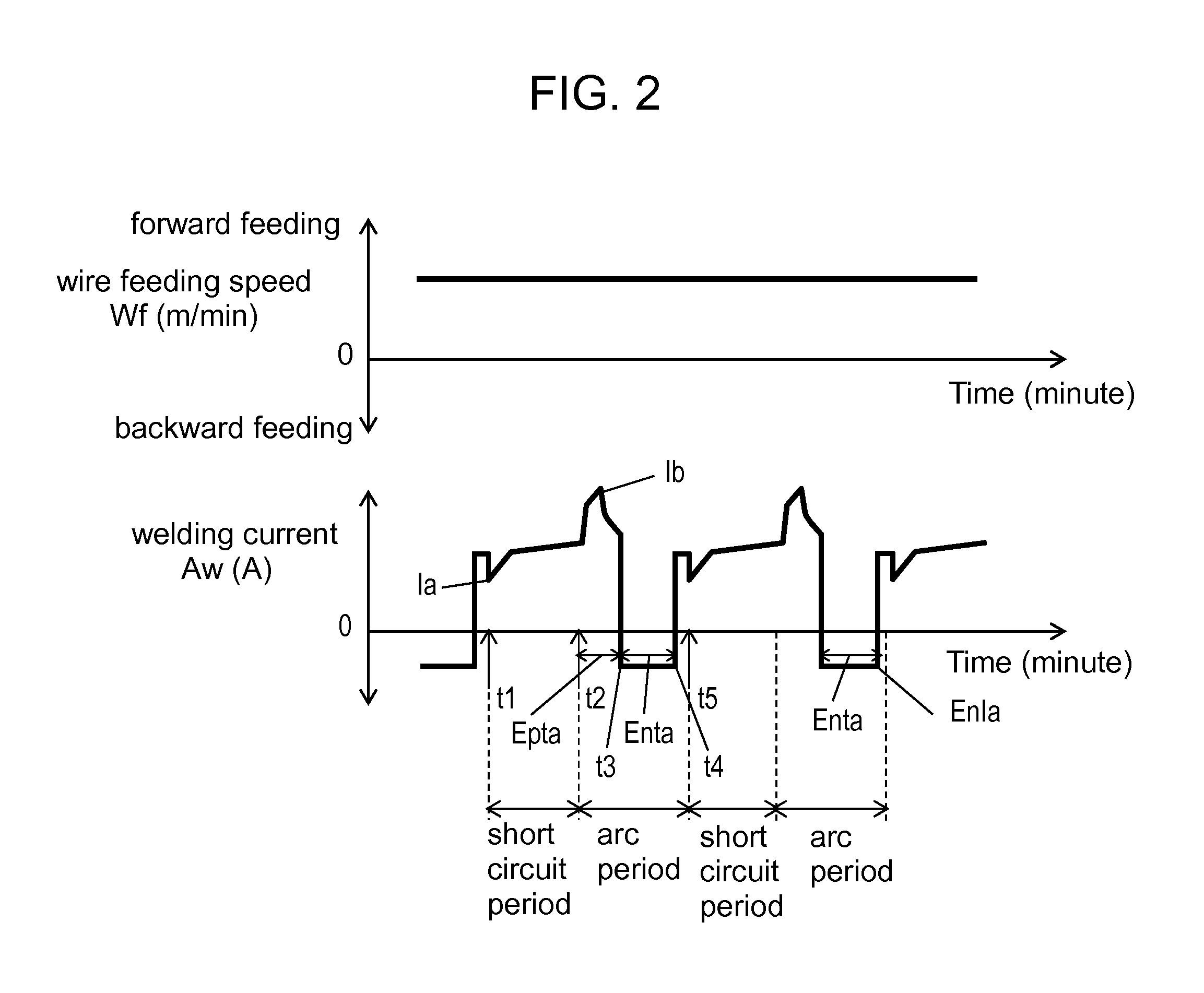
[0017]FIG. 1 is a diagram showing a schematic structure of arc welding apparatus 1 of a consumable electrode type according to a first exemplary embodiment of the present invention. FIG. 2 is a chart showing temporal waveforms of a wire feeding speed and a welding current in the case in which welding is carried out by the arc welding control method of a consumable electrode type according to the first exemplary embodiment of the present invention.

[0018]As shown in FIG. 1, arc welding apparatus 1 includes primary side rectifying unit 3, switching unit 4, main transformer 5, secondary side rectifying unit 6, rector 7, welding current detecting unit 8, welding voltage detecting unit 9, short circuit / arc detecting unit 10, output control unit 11, polarity inversion setting unit 12, polarity inversion output control unit 13, polarity inversion switching unit 14, and wire feeding speed control unit 16. Primary side rectifying unit 3 rectifies an input voltage (an input AC power) which is ...

second exemplary embodiment

[0049]A second exemplary embodiment according to the present invention is mainly different from the first exemplary embodiment in that an operator can adjust first predetermined time Epta and second predetermined time Enta which are times that the first commutation and the second commutation are to be carried out for the arc period, respectively.

[0050]An arc welding apparatus according to the second exemplary embodiment is constituted by the same components as those in arc welding apparatus 1 of a consumable electrode type shown in FIG. 1, and therefore, an operation thereof will be described with reference to FIG. 1. In the second exemplary embodiment, welding condition setting unit 15 shown in FIG. 1 has a function for adjusting first predetermined time Epta or second predetermined time Enta. Consequently, the operator can adjust first predetermined time Epta or the second predetermined time Enta. More specifically, welding condition setting unit 15 is provided with an adjusting a...

third exemplary embodiment

[0056]A third exemplary embodiment according to the present invention is mainly different from the first exemplary embodiment in that forward feed and backward feed are cyclically repeated in a predetermine cycle and a predetermined amplitude as the feed of wire 20.

[0057]FIG. 3 is a chart showing an output waveform of an arc welding control method according to the third exemplary embodiment of the present invention, illustrating temporal waveforms for wire feeding speed Wf and welding current Aw in the case in which welding is carried out by an arc welding control method of a consumable electrode type. The feed of wire 20 is controlled to repeat the forward feeding and the backward feeding as shown in wire feeding speed Wf of FIG. 3.

[0058]In the case in which wire feeding speed Wf indicates the forward feeding, that is, wire 20 is fed in a direction of base metal 22, there is a tendency that a short circuit is apt to be caused in the vicinity of wire feeding speed Wf1 having a high ...


PUM

PropertyMeasurementUnit
thicknessaaaaaaaaaa
thicknessaaaaaaaaaa
timeaaaaaaaaaa

Abstract

In an arc welding control method of repeating a short circuit and an arc to perform welding, control is carried out to conduct a welding current having a first polarity for a short circuit period, and a first commutation to commutate the welding current from the first polarity to be a polarity of the welding current for the short circuit period to a second polarity to be opposite to the first polarity is carried out for an arc period subsequent to the short circuit period. Furthermore, control is performed to carry out a second commutation to commutate the welding current from the second polarity to the first polarity for the arc period in which the first commutation is executed. Consequently, it is possible to reduce an energy input amount to a base metal, thereby suppressing burn-through in welding of a thin plate.

Description

TECHNICAL FIELD[0001]The present invention relates to an arc welding control method of a consumable electrode type and an arc welding apparatus of a consumable electrode type which alternately generate a short circuit state and an arc state to carry out welding while feeding a welding wire to be a consumable electrode.BACKGROUND ART[0002]In recent years, in the welding industry, it is greatly demanded to increase a welding speed or to reduce sputtering in order to enhance productivity. In order to meet these demands, an arc welding apparatus of a consumable electrode type is developed and an arc welding control method is devised. However, there is not devised an arc welding control method of reducing an energy input of welding so as not to cause burn-through or the like due to welding of a thin plate.[0003]FIG. 4 is a chart showing an output waveform in a conventional arc welding control method accompanied by a short circuit, illustrating a time variation in a wire feeding speed Wf ...

Claims


Application Information

Patent Timeline
Patent Type & Authority Applications(United States)
IPC IPC(8): B23K33/00
CPCB23K9/092B23K9/173B23K9/0953
Inventor MATSUI, KAITOKAWAMOTO, ATSUHIROHIROTA, YUKINORI
Owner PANASONIC INTELLECTUAL PROPERTY MANAGEMENT CO LTD
Why Eureka
Try Eureka