

Synchronizer with high reliability
a synchronizer and high reliability technology, applied in the field of computing systems, can solve the problems of inability to perform computations, delay in subsequent combinatorial logic, and inability to provide wrong signals, etc., and achieve the effect of high reliability and efficient synchronization of asynchronous input signals
- Summary
- Abstract
- Description
- Claims
- Application Information
AI Technical Summary
Benefits of technology
Problems solved by technology
Method used
Image

Examples
Embodiment Construction
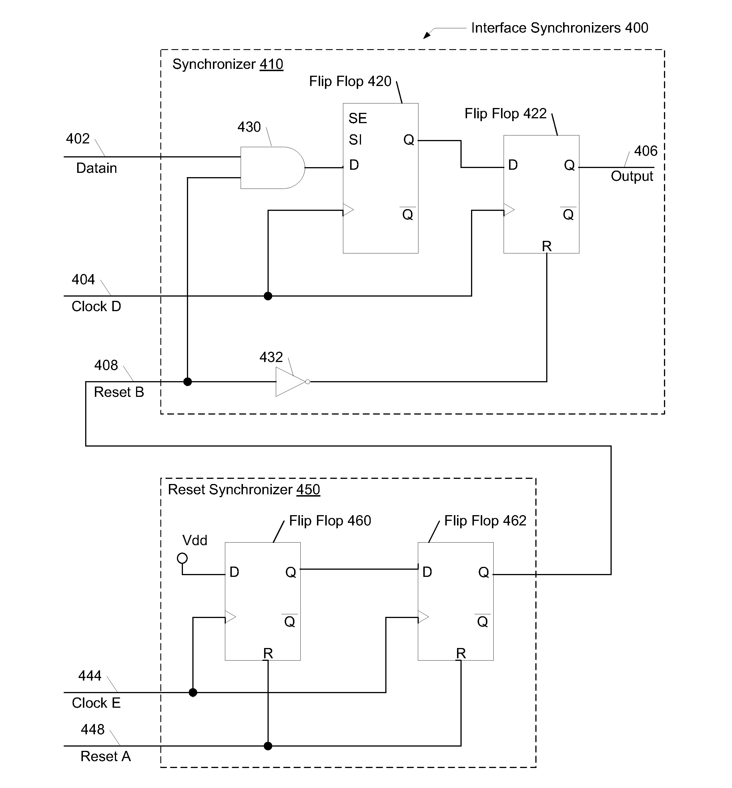
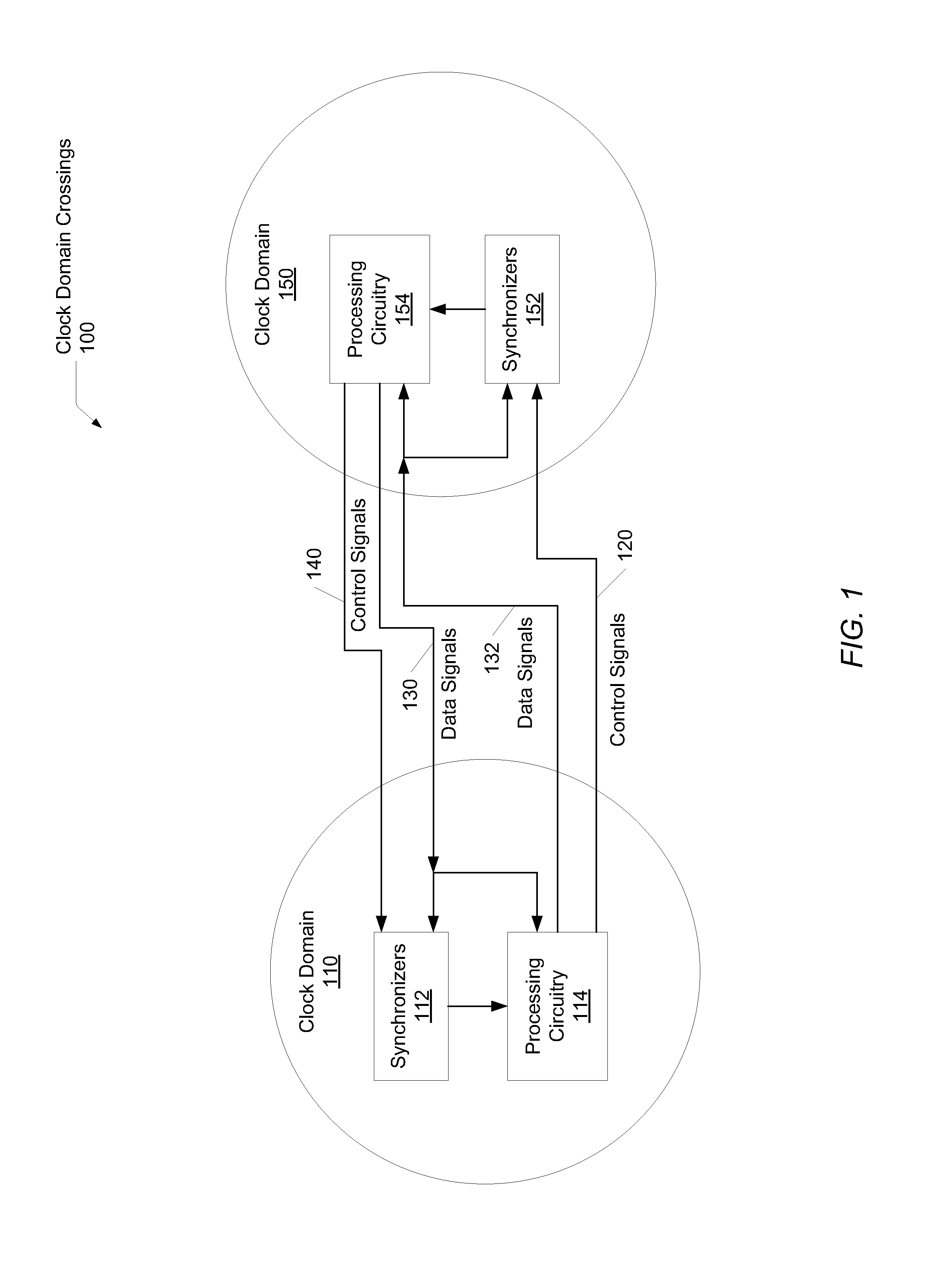
[0009]Systems and methods for efficiently synchronizing asynchronous input signals with high reliability. In one embodiment, an interface between two clock domains includes a synchronizer. The interface may be placed in an interface unit on a system-on-a-chip (SOC). Alternatively, the interface may be placed within a processor. The synchronizer may include at least two storage elements coupled together in a cascaded manner. Each of the storage elements may receive a first clock signal in a first clock domain. Control logic within the synchronizer may combine an asynchronous data input signal and the first reset signal. The data input signal may be generated from circuitry utilizing a second clock domain different from the first clock domain. The first and the second clock domain may differ by having a different clock frequency, a different clock duty cycle and / or by having a nonzero phase relation between them.
[0010]A first storage element may receive a value based on the combinatio...
PUM
 Abstract
Description
Claims
Application Information