
Apparatus and method for synchronizing wireless devices

Active Publication Date: 2012-05-10
SIMMONDS PRECISION PRODS
View PDF5 Cites 7 Cited by
  • Summary
  • Abstract
  • Description
  • Claims
  • Application Information

AI Technical Summary

Benefits of technology

[0013]The subject disclosure has recognized and addressed the need to effectively synchronize sensors and other system elements that communicate wirelessly using high level commercial protocols. In one method, commercially available high level protocols, such as TCP, are used for reliable wireless transmission of sensor data. However for synchronization purposes, the method switches operation to a less complicated, potentially less reliable, but simpler protocol with limited and / or more consistent latency, such as UDP. In order to accommodate the higher message losses associated with the simpler protocol, a number of approaches are developed to still efficiently complete accurate synchronization calculations. Hence, the method allows utilizing the high reliability of complex packet-based commercial-off-the-shelf protocols for data transfer while still allowing for tight synchronization. As a result, the cost and development effort of the wireless sensing systems is desirably lower.

Problems solved by technology

There are problems associated with high level communication protocols when synchronizing is required because, there is uncertainty about the exact time of delivery.
The latency of a particular message cannot be fully predicted due to high level protocols such as TCP using multiple software layers as well as complicated acknowledgement, retransmission, and packet scheduling algorithms.
The unpredictable latency creates a difficulty with performing synchronization of end devices using these high level protocols.
However for synchronization purposes, the method switches operation to a less complicated, potentially less reliable, but simpler protocol with limited and / or more consistent latency, such as UDP.
As a result, the cost and development effort of the wireless sensing systems is desirably lower.

Method used


Image

  • Apparatus and method for synchronizing wireless devices
  • Apparatus and method for synchronizing wireless devices
  • Apparatus and method for synchronizing wireless devices

Examples


Embodiment Construction

[0027]The present disclosure overcomes many of the prior art problems associated with synchronizing wireless systems. The advantages, and other features of the system disclosed herein, will become more readily apparent to those having ordinary skill in the art from the following detailed description of certain preferred embodiments taken in conjunction with the drawings which set forth representative embodiments of the present invention and wherein like reference letters and numerals identify similar structural elements.

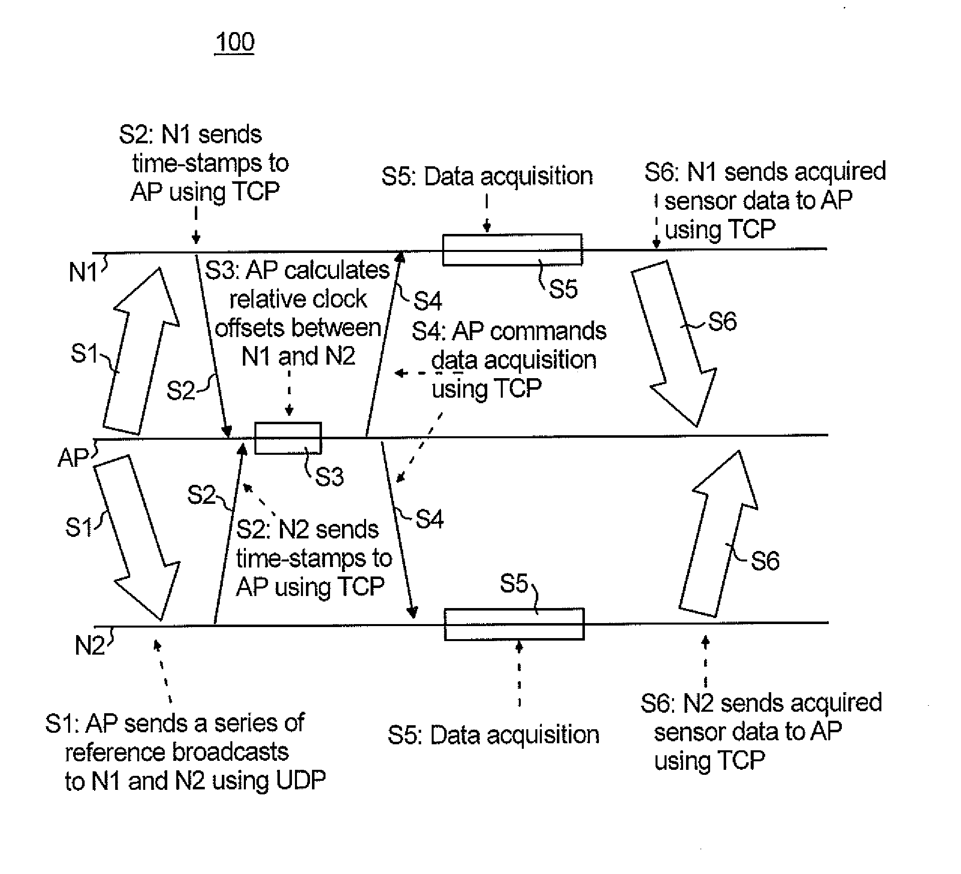
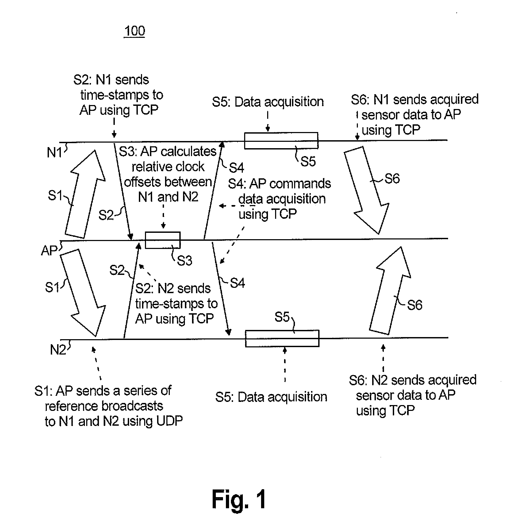
[0028]Now referring to FIG. 1, a flowchart 100 illustrating a synchronization method for wireless sensors in accordance with the subject technology is shown. The synchronization method 100 is for a system having sensors that use the highly reliable TCP protocol for most message exchanges including data acquisition commands from a central access point node AP and transmission of the acquired sensor data to the central access point node AP.

[0029]For exchanges of synchr...


PUM


Abstract

An apparatus for synchronizing devices includes a central access point node configured to utilize a low latency protocol to transmit a series of synchronization messages to the devices, transmit and receive data acquisition commands and responses from the devices using a high reliability protocol different from the low latency protocol, and calculate and apply relative clock offsets for each device based on the series of synchronization messages. The apparatus may also account for failure in delivery of a portion of the series of synchronization messages by recording timestamp data at the devices to send to the central access point prior to the central access point calculating the relative clock offsets.

Description

BACKGROUND OF THE DISCLOSURE[0001]1. Field of the Disclosure[0002]The subject disclosure relates to communication in sensing, monitoring and control systems, and more particularly to synchronizing wireless devices used on board aircraft.[0003]2. Background of the Related Art[0004]In recent years, the aerospace industry has been actively working on using wireless communication as a replacement for wired data connections in aircraft systems. Some benefits of wireless as opposed to traditionally wired sensor include weight and complexity reductions, simplified installation and maintenance, easier system reconfiguration as well as better diagnostic analysis. Additionally, new sensing technologies and aircraft subsystems are enabled by utilizing wireless technology, which eliminates additional design and installation costs and limits the additional wiring weight.[0005]Mechanical and structural health monitoring and diagnostic systems particularly benefit from wireless technology. At pres...

Claims


Application Information

Patent Timeline
IPC IPC(8): G06F15/16
CPCH04J3/0667H04L69/165H04W4/005H04W4/70
Inventor LYNCH, MICHAEL A.ZAKRZEWSKI, RADOSLAW R.
Owner SIMMONDS PRECISION PRODS
Learn More