
Systems and Methods of Dual-Plane Digital Holographic Microscopy

a digital holographic and dual-plane technology, applied in the field of digital holographic microscopy, can solve the problems of inability to measure certain biological parameters of specimens using techniques, difficult to see the phase structure of objects with naked eyes or ordinary imaging techniques, and inability to use techniques to measure certain biological parameters

Active Publication Date: 2013-03-21
UNIV OF MASSACHUSETTS
View PDF4 Cites 23 Cited by
  • Summary
  • Abstract
  • Description
  • Claims
  • Application Information

AI Technical Summary

Benefits of technology

This patent describes a system for digital holographic microscopy that uses multiple optical elements to create interfered optical waves, which are then recorded using a special imaging device. The system has several technical effects, including improved image quality and reduced blurring, which make it easier to analyze and observe small specimens.

Problems solved by technology

Hence, the phase structure of these objects are difficult to see with naked eyes or ordinary imaging techniques, which are only sensitive to the amplitude component of optical waves.
However the phase information provided by these techniques is only qualitative.
As such, these techniques cannot be used to measure certain biological parameters of specimens, such as intracellular refractive indices, because measuring such biological parameters requires measuring phase structure of the biological specimen quantitatively.
Unfortunately, off-axis interferometry requires a spatial filtering during numerical reconstruction that separates the desired positive-order diffracted waves, and the unwanted zero- and negative-order diffracted waves.
This spatial filtering process limits the spatial resolution of the reconstructed image.
Since a relatively long time is required for applying the phase shifts and acquiring the interferograms, this method of phase-shifting is not suitable for recording dynamic processes.
In addition, on-axis phase-shifting interferometry is also prone to phase-shift calibration errors, and system fluctuations that may occur while capturing multiple interferograms.
However, Zhang's optical system is tailored to reconstructing amplitude objects only and is incapable of reconstructing phase objects.
Therefore, Zhang's optical system is incapable of imaging object with both amplitude and phase structures.
FIG. 4 experimentally shows that Zhang's system fails to recover the phase structure of phase objects, and FIG. 6 experimentally shows that Zhang's system also does a poor job in recovering the amplitude structure of amplitude objects due to the impractical weak-object wave assumption.
Therefore, Zhang's optical system cannot accurately recover either the amplitude structure or the phase structure of specimens.

Method used


Image

  • Systems and Methods of Dual-Plane Digital Holographic Microscopy
  • Systems and Methods of Dual-Plane Digital Holographic Microscopy
  • Systems and Methods of Dual-Plane Digital Holographic Microscopy

Examples


Embodiment Construction

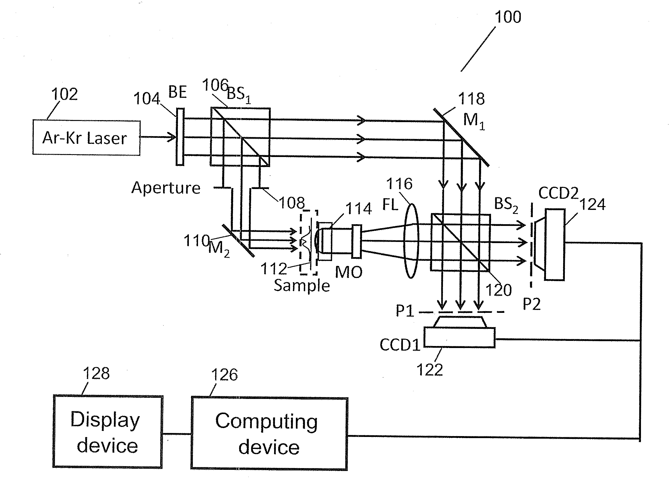
[0028]Embodiments of the present invention are directed to systems and methods of an in-line digital holographic microscopy (DHM) that is configured to record a plurality of interferograms associated with microscopic specimens and to recover from the plurality of inteferograms the amplitude information and the phase information of the microscopic specimens. Because the plurality of interferograms can be recorded substantially simultaneously, embodiments of the present invention can record fast dynamic processes such as cell membrane fluctuations, cell swelling, neuronal activity, and cytoskeletal dynamics.

[0029]In-Line Dual-Plane DHM (ID-DHM)

[0030]Generally, in-line DHM uses a coherent light source to illuminate a specimen that is located in an optical path between the light source and an image plane. In-line DHM is configured to illuminate the specimen along the axis normal to the image plane; the optical waves passing through the specimen are called the object waves. In-line DHM i...


PUM


Abstract

An embodiment of the disclosed DHM system includes a light source configured to emit coherent optical waves, a first optical Fourier element configured to Fourier transform the optical waves from the object area, wherein the Fourier transform occurs at a Fourier plane and the optical waves from the object area includes directly transmitted waves and diffracted waves, a phase modulator at the Fourier plane configured to introduce a phase delay between the directly transmitted waves and the diffracted waves, a second optical Fourier element configured to receive the directly transmitted waves and the diffracted waves from the phase modulator and to inversely Fourier transform the directly transmitted waves and the diffracted waves to provide interfered optical waves, and at least one imaging device configured to record the interfered optical waves at two image planes to generate a first interferogram and a second interferogram.

Description

CROSS REFERENCE TO RELATED APPLICATIONS[0001]This application is related to U.S. Pat. No. 7,738,047 and U.S. Pat. No. 7,880,820, entitled “Systems and Methods of All-Optical Fourier Phase Contrast Imaging using Dye Doped Liquid Crystals,” the entire contents of which are incorporated herein by reference.STATEMENT REGARDING FEDERALLY SPONSORED RESEARCH OR DEVELOPMENT[0002]This invention was made with government support under 1R21RR024429-01A1 awarded by National Institute of Health. The government has certain rights in the invention.BACKGROUND[0003]1. Field[0004]The disclosed subject matter generally relates to digital holographic microscopy.[0005]2. Discussion of Related Art[0006]Numerous biological samples, including live cells, are generally transparent under visible-light illumination and behave essentially as phase objects. Phase objects can only alter the phase component of optical waves, not their amplitude component. Hence, the phase structure of these objects are difficult t...

Claims


Application Information

Patent Timeline
IPC IPC(8): G01B9/021
CPCG03H2223/52G03H1/0443G03H2210/10G02B21/365G02B26/06G03H1/0005G03H1/0866G03H2001/005G03H2001/0447G03H2001/0454G03H2210/12G03H2223/13G03H2223/55G03H2226/13G03H2001/0471
Inventor DAS, BHARGABYELLESWARAPU, CHANDRA S.RAO, D.V.G.L.N
Owner UNIV OF MASSACHUSETTS
Learn More