High Speed Multi-Mode Fiber Transmissions via Orthogonal Wavefronts

Inactive Publication Date: 2013-03-21
CHANG DONALD C D
View PDF1 Cites 15 Cited by
  • Summary
  • Abstract
  • Description
  • Claims
  • Application Information

AI Technical Summary

Benefits of technology

[0018]The equipment used for communications over MMF optical fibers is much less expensive than that for single-mode optical fiber. Because of its high capacity and reliability, multi-mode optical fiber generally is used for backbone applications in buildings, airborne platforms, ground/sea based moving platforms. An increasing number of users are taking the benefits of fiber closer to the user by running fiber to the desktop or to the zone. For a high rise building, standards-compliant architectures such as Centra

Problems solved by technology

The capacity of a single fiber channel is adequate enough only to have one signal stream delivered, but not wide enough to have both signals streams delivered concurrently.
The second limiting c

Method used


Image

  • High Speed Multi-Mode Fiber Transmissions via Orthogonal Wavefronts
  • High Speed Multi-Mode Fiber Transmissions via Orthogonal Wavefronts
  • High Speed Multi-Mode Fiber Transmissions via Orthogonal Wavefronts

Examples


Embodiment Construction

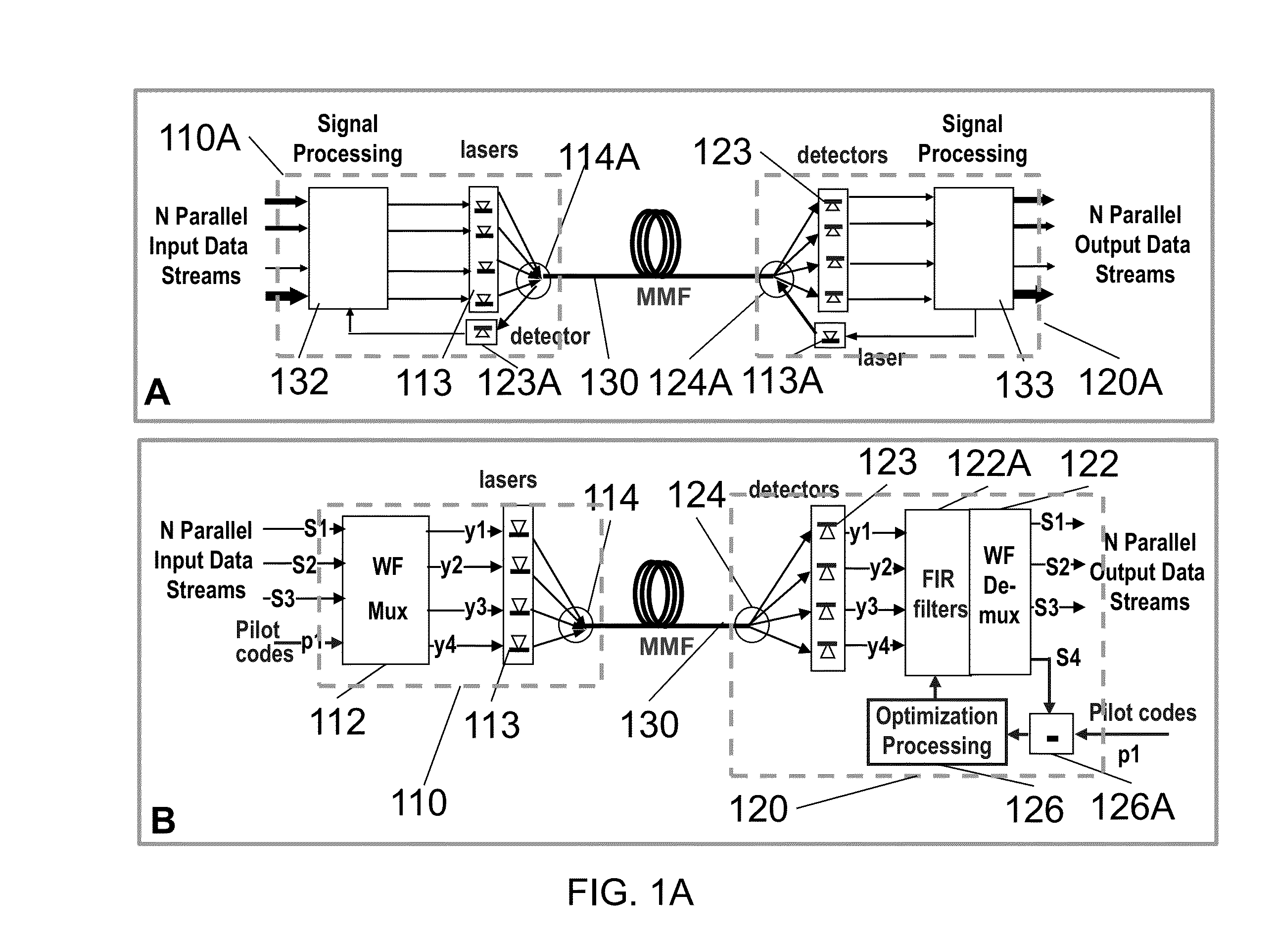
[0066]The current invention provides a system for coherently bonding multiple optical fiber communication channels by generating artificial wavefronts in multiple optical paths that exhibit mutual spatial orthogonality. Multiple independent signal streams are “structured” over a group of different propagation paths coherently organized by wavefront (WF) multiplexing (muxing) and de-multiplexing (demuxing) techniques. In the detailed description that follows, like element numerals are used to indicate like elements appearing in one or more of the figures.

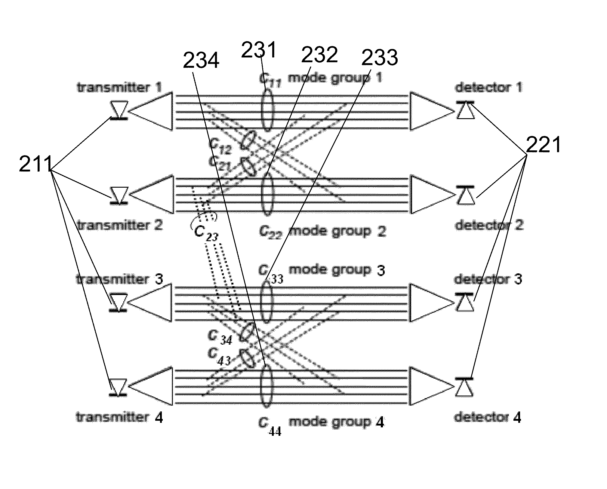
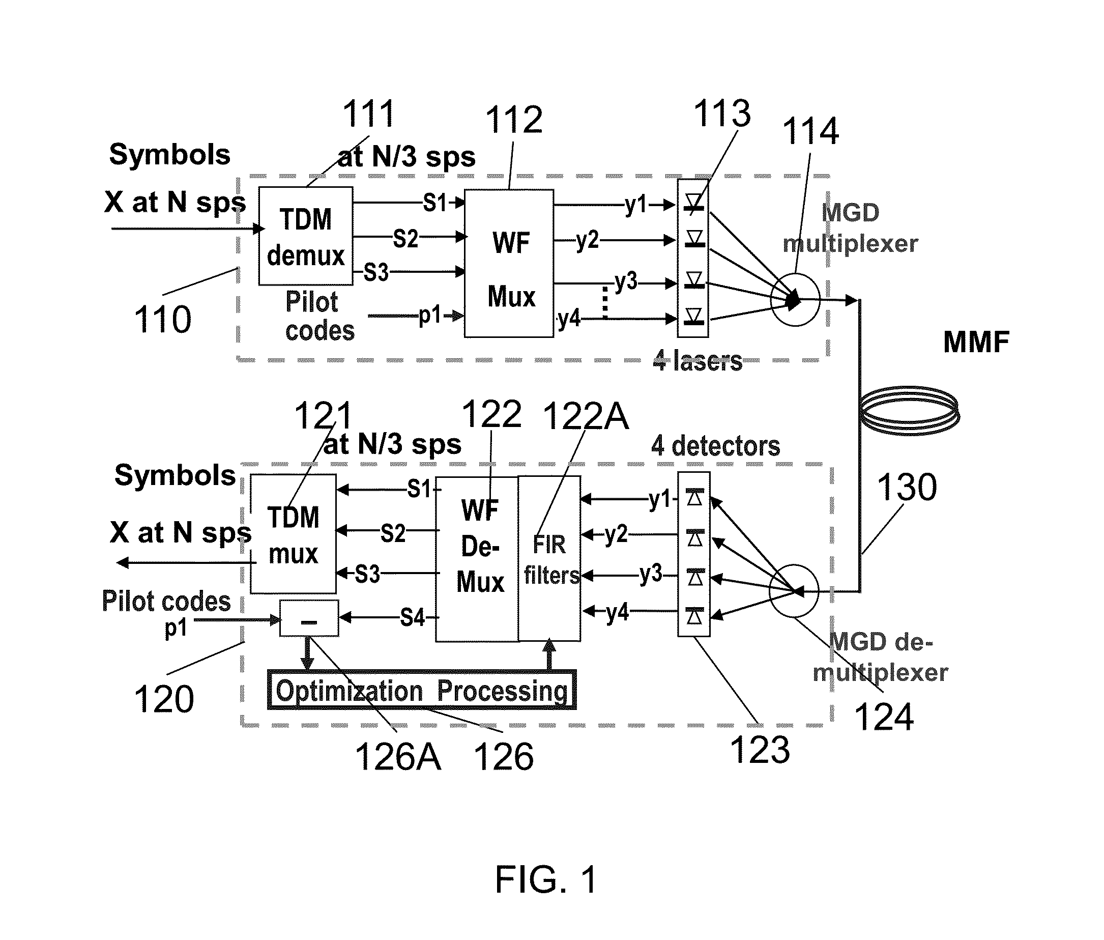
[0067]FIG. 1 illustrates a design concept featuring a multiple-mode-fiber (MMF) with 300% improved transmission capacity via 4 separated mode-groups (MGs) organized by a WF muxing and demuxing processor. It is only for illustrations of a point-to-point design concept and is not an implementation design.

[0068]Each MG features a vertical-cavity surface-emitting laser (VCSEL) 113 in transmission site and associated detector 123 on recei...


PUM


Abstract

A system is provided for high speed optical fiber data transmission by generating artificial wavefronts along multiple paths exhibiting spatial mutual orthogonality. Multiple independent signal streams are “structured” over a group of different propagation paths that are coherently organized by wavefront multiplexing and de-multiplexing techniques. Therefore, signal streams with enhanced throughput and reliability may be fully recovered at destinations via embedded diagnostic signals and optimization loops. Multiple optical channels are matched with multiple orthogonal wavefronts created by a signal pre-processor. A receiving end signal post-processor dynamically aligns propagation paths via diagnostic signals and orthogonality of the propagation wavefronts electronically. The multiple optical channels are coherently bonded into a single virtual channel, thereby increasing data bandwidth while reducing interference and unwanted multi-path effects. The wavefront multiplexing and de-multiplexing functions may be performed in a dedicated signal processor or may reside in a general-purpose microprocessor located in the user terminal.

Description

RELATED APPLICATION DATA[0001]This application claims the benefit, pursuant to 35 U.S.C. .sctn.119(e), of U.S. provisional application Ser. No. 60 / 930,958, filed May 21, 2007, and U.S. provisional application Ser. No. 60 / 930,957, filed May 21, 2007.BACKGROUND OF THE INVENTION[0002]1. Field of the Invention[0003]The present invention relates to techniques for improving the throughput and reliability of optical fiber links by coherently bonding multiple communication channels together. More particularly, the invention relates to techniques for using multiple orthogonal wavefronts propagating concurrently through multiple optical paths in a fiber to provide enhanced communications via increased channel bandwidth. Furthermore, the same techniques can be modified to enhance amplified signal power thus increasing the effective communications range of the optical data communications[0004]2. Description of Related Art[0005]It is well known in the art that increasing the bandwidth and reliab...

Claims


Application Information

Patent Timeline
IPC IPC(8): H04J14/02H04B10/08G01S13/933
CPCG01S13/9303H04L25/03891G01S7/006H04B7/18502H04B7/2041B64C39/02H04B7/18504H04B7/18515H04B7/18517H04B7/18523G01S13/933H04B10/2581H04J14/02H04B7/0413H04J14/00H04J14/005H04J14/08H04L25/03006
Inventor CHANG, DONALD C. D.
Owner CHANG DONALD C D
Why Eureka
Try Eureka