Eureka AIR delivers breakthrough ideas for toughest innovation challenges, trusted by R&D personnel around the world.

Film deposition apparatus and substrate processing apparatus

Inactive Publication Date: 2013-03-28
TOKYO ELECTRON LTD
View PDF6 Cites 10 Cited by
  • Summary
  • Abstract
  • Description
  • Claims
  • Application Information

AI Technical Summary

Benefits of technology

The present invention is a film deposition apparatus and substrate processing apparatus. It can reduce the flow rate of a separation gas, which prevents process gases from mixing with each other during processing. The separation gas is supplied to a specific location between the areas where the process gases are respectively supplied. This results in the deposition of a reaction product on the surface of a substrate in a layer-by-layer manner. The technical effect of this invention is to improve the quality and efficiency of film deposition and substrate processing.

Problems solved by technology

At this time, if the separation gas is supplied at a greater flow rate, a running cost of the apparatus (i.e. , cost of the separation gas) increases.
Moreover, there is a concern that the process gases are diluted by the separation gas.
In contrast, if the flow rate of the separation gas is assumed to be reduced, there is a concern that the process gases are mixed with each other in a processing atmosphere.
U.S. Pat. No. 7,153,542, Japanese Patent No. 3144664, and U.S. Pat. No. 6,869,641 disclose apparatuses that deposit a thin film by the ALD method, but do not disclose measures to address the above mentioned concerns.

Method used


Image

  • Film deposition apparatus and substrate processing apparatus
  • Film deposition apparatus and substrate processing apparatus
  • Film deposition apparatus and substrate processing apparatus

Examples


Embodiment Construction

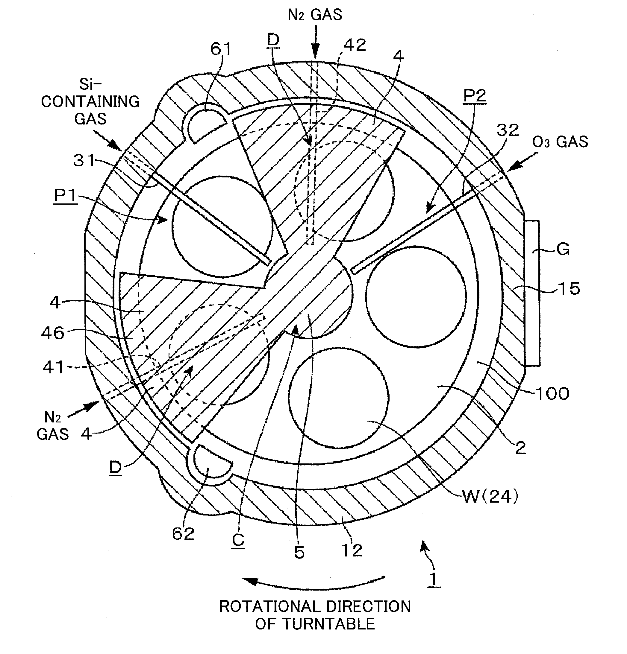
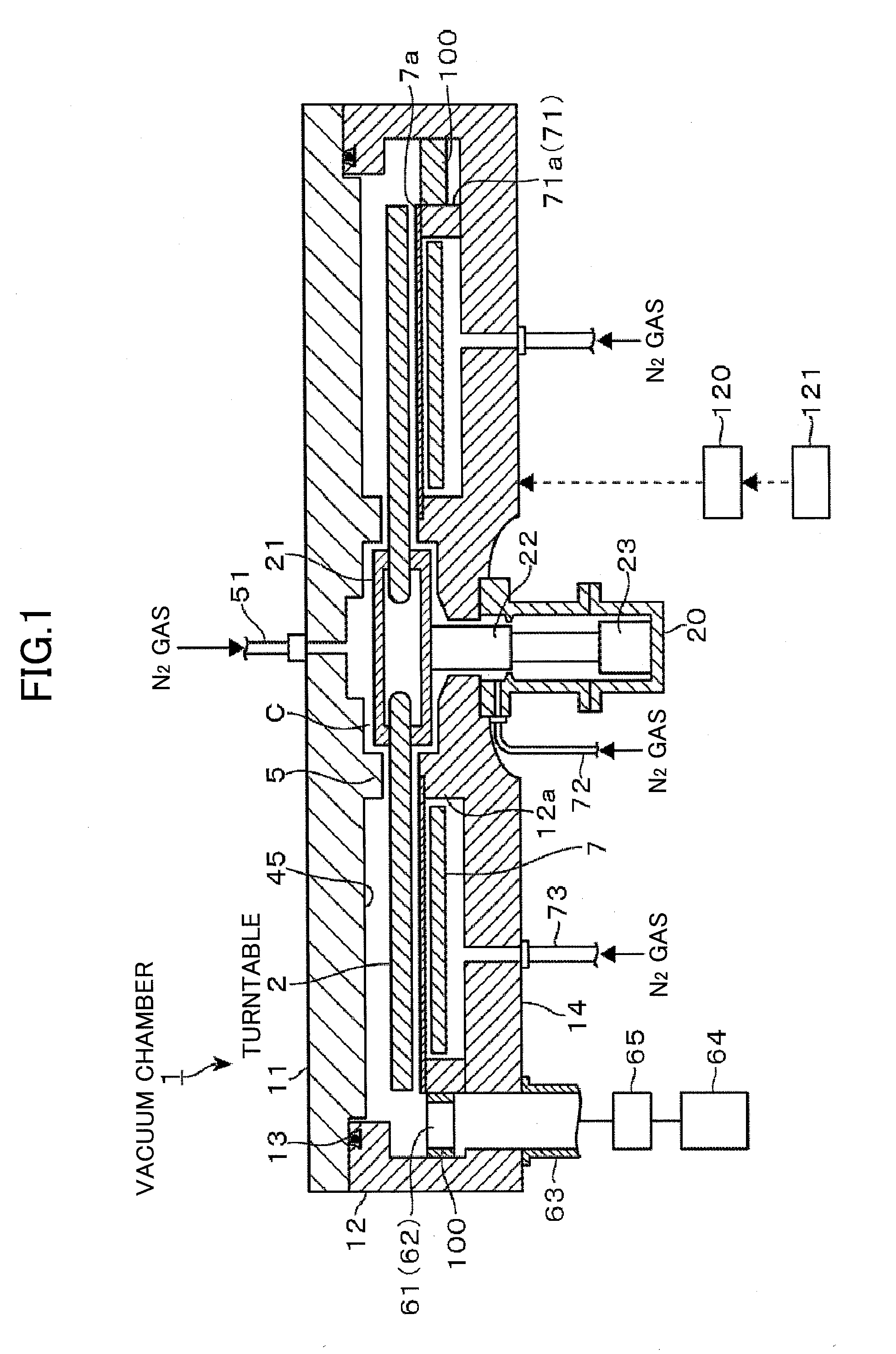
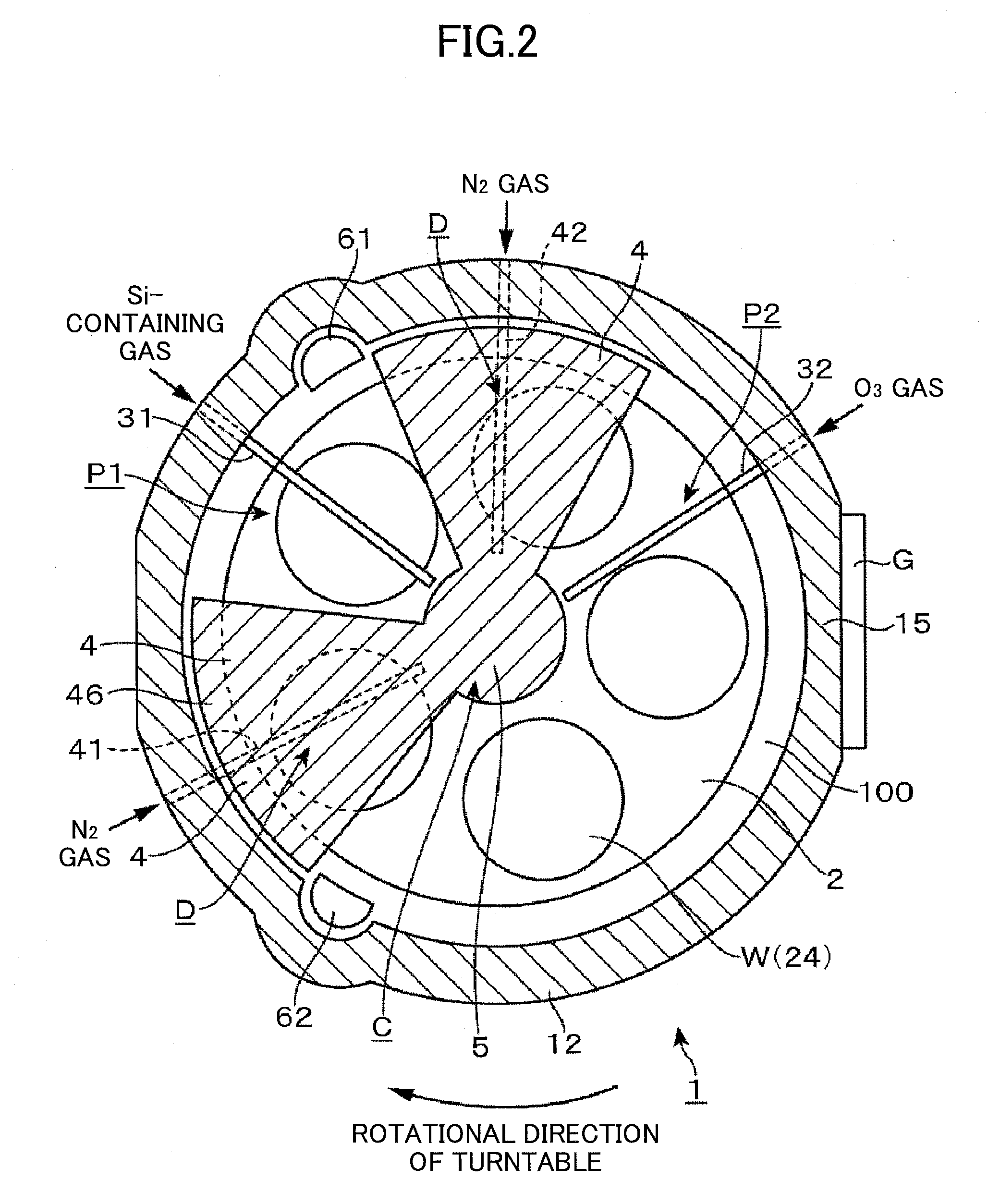
[0026]A description is given below, with reference to drawings of embodiments of the present invention. More specifically, a description is given about an example of a substrate processing apparatus of an embodiment of the present invention with reference to FIGS. 1 through 8. As shown in FIGS. 1 and 2, a film deposition apparatus of an embodiment of this substrate processing apparatus includes a vacuum chamber 1 whose planar shape is an approximately round shape, and a turntable 2 provided in the vacuum chamber 1 and having the rotation center that coincides with the center of the vacuum chamber 1. As described below in detail, the film deposition apparatus deposits a thin film by supplying plural process gases that react with each other, for example, two kinds of process gases, on a wafer W by an ALD method, and sections areas to which these process gases are respectively supplied by using a separation gas. At this time, a supply flow rate of the separation gas is kept low so that...


PUM

PropertyMeasurementUnit
Lengthaaaaaaaaaa
Areaaaaaaaaaaa

Abstract

A film deposition apparatus includes processing areas spaced part from each other in a circumferential direction and at least one separation gas nozzle arranged between the process areas, and separates the process areas from each other by supplying a separation gas from the separation gas nozzle. Moreover, a first ceiling surface is provided on the downstream side in a rotational direction of the turntable relative to the separation gas nozzle to form a narrow space between an upper surface of the turntable and a lower surface of the first ceiling surface. Furthermore, a second ceiling surface higher than the first ceiling surface is provided on the upstream side in the rotational direction of the turntable.

Description

CROSS-REFERENCE TO RELATED APPLICATIONS[0001]This patent application is based upon and claims the benefit of priority of Japanese Patent Application No. 2011-207990, filed on Sep. 22, 2011, the entire contents of which are incorporated herein by reference.BACKGROUND OF THE INVENTION[0002]1. Field of the Invention[0003]The present invention relates to a film deposition apparatus and a substrate processing apparatus that deposit a reaction product on a surface of a substrate in a layer-by layer manner by supplying process gases that react with each other.[0004]2. Description of the Related Art[0005]An apparatus is known that deposits a thin film such as a silicon oxide film (SiO2) on a substrate such as a semiconductor wafer (which is hereinafter called a “wafer”) by using an ALD (Atomic Layer Deposition) method. As disclosed in Japanese Patent Application Laid-Open Publication No. 2010-239102, for example, such an apparatus has a configuration in which a turntable on which plural waf...

Claims


Application Information

Patent Timeline
IPC IPC(8): C23C16/458
CPCC23C16/401C23C16/4585C23C16/45548C23C16/45521
Inventor HONMA, MANABU
Owner TOKYO ELECTRON LTD
Why Eureka
Eureka Blog
Learn More