System and method for fluid processing with variable delivery for downhole fluid analysis

a technology of fluid analysis and system, applied in the field of system and method, can solve the problem of limited number of components that can be determined directly by spectroscopic techniques, and achieve the effect of avoiding exposure to a local environmen

Active Publication Date: 2013-03-28
SCHLUMBERGER TECH CORP
View PDF5 Cites 29 Cited by
  • Summary
  • Abstract
  • Description
  • Claims
  • Application Information

AI Technical Summary

Benefits of technology

[0013]In some embodiments, the device includes one or more of an isolation valve disposed between the sample port and the fluid conduit and a filter in fluid communication with the sample port. A windowed fluid conduit can be provided in serial fluid communication with the fluid conduit between the mixer and the open end of the second variable-volume reservoir. An illumination source and detector can be arranged in view of the windowed fluid conduit, such that the source-detector combination allows for observation of optical properties of the mixture of the reactant and the sampled fluids.
[0015]In at least some embodiments, one or more of the first, second and third variable-volume reservoirs can include a pressure-balance port in fluid communication with the flowline. Such a pressure balance port enables volume variation of the respective variable-volume reservoir having its open end exposed to a flowline pressure without having to overcome flowline pressure.
[0018]In at least some embodiments, the process further includes collecting a waste portion of the reagent-sample mixture, thereby avoiding exposure to a local environment. Collecting the reagent-sample mixture can include, for example, injecting at least a portion of the reagent-sample mixture into the flow of high-pressure fluids.

Problems solved by technology

However, the number of components that can be determined directly by spectroscopic techniques is limited.

Method used


Image

  • System and method for fluid processing with variable delivery for downhole fluid analysis
  • System and method for fluid processing with variable delivery for downhole fluid analysis
  • System and method for fluid processing with variable delivery for downhole fluid analysis

Examples


Embodiment Construction

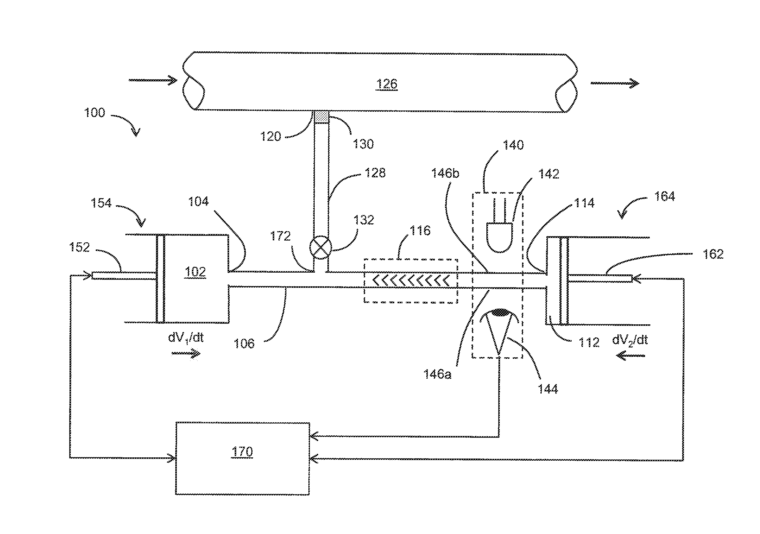
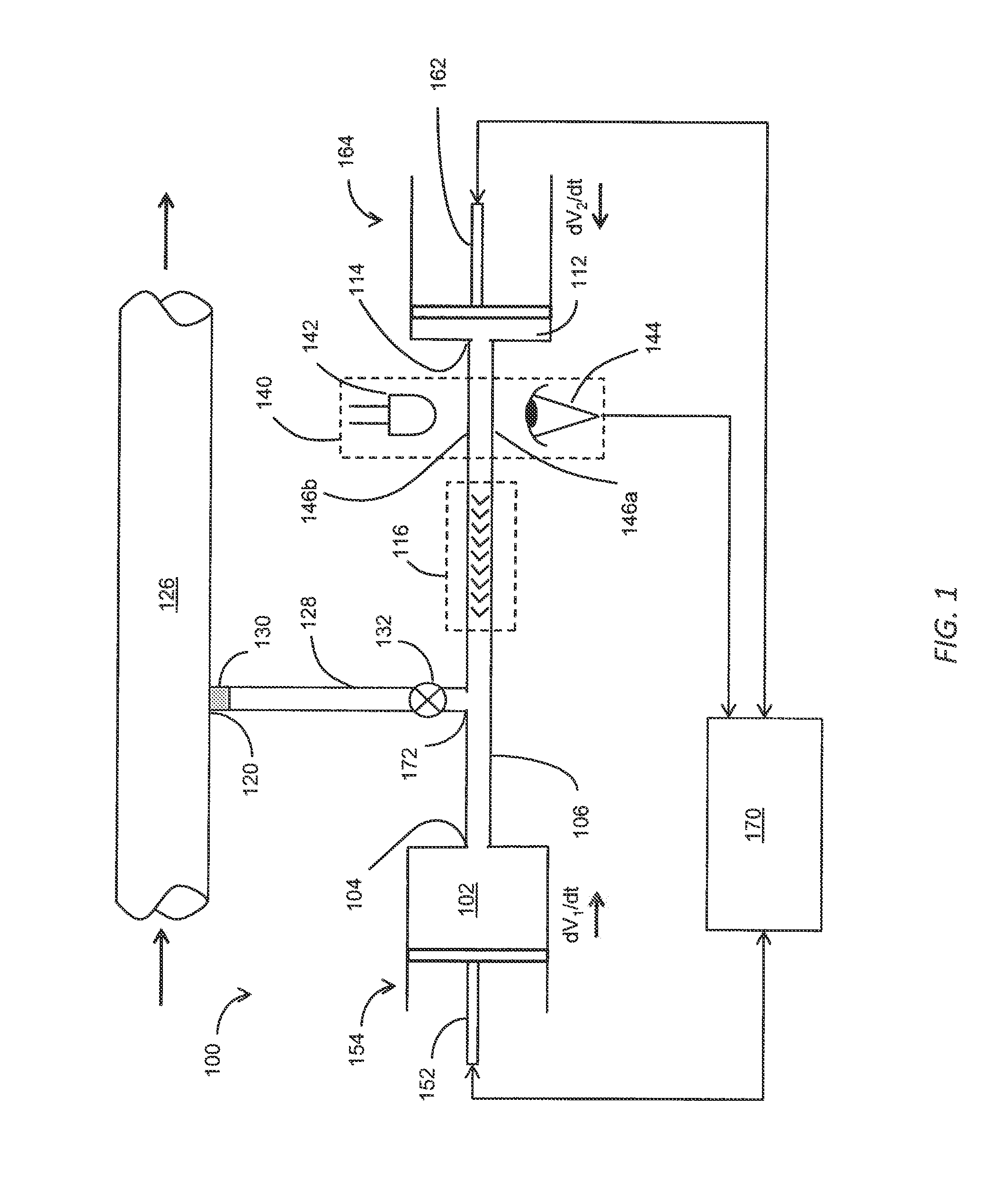
[0040]In the following detailed description of the preferred embodiments, reference is made to accompanying drawings, which form a part thereof, and within which are shown by way of illustration, specific embodiments, by which the invention may be practiced. It is to be understood that other embodiments may be utilized and structural changes may be made without departing from the scope of the invention.

[0041]The particulars shown herein are by way of example and for purposes of illustrative discussion of the embodiments of the present invention only and are presented in the case of providing what is believed to be the most useful and readily understood description of the principles and conceptual aspects of the present invention. In this regard, no attempt is made to show structural details of the present invention in more detail than is necessary for the fundamental understanding of the present invention, the description taken with the drawings making apparent to those skilled in t...


PUM


Abstract

Described herein are variable-volume reservoir (e.g., syringe pump) based processes and systems usable to characterize samples of reservoir fluids, without having to first transport the fluids to the surface. Variable-volume reservoirs are used, for example, for one or more of storing reactants, controlling mixing ratios and storing used chemicals. The processes and systems can be used in various modes, such as continuous mixing mode, flow injection analysis, and titrations. A fluid interrogator, such as a spectrometer, can be used to detect a change in a physical property of the mixture, which is indicative of an analyte within the mixture. In at least some embodiments, a concentration of the analyte solution can be determined from the detected physical property.

Description

BACKGROUND[0001]1. Technical Field[0002]This application relates generally to fluid processing. More particularly, this application relates to chemical analysis of fluid samples within a wellbore environment.[0003]2. Background Information[0004]Chemical analysis is a critical step in the evaluation of the hydrocarbon reserves. The fluid / gas composition has a large impact on the economic value of the reservoir. Furthermore, the fluid / gas composition determines the well completion and production strategies. Traditionally, samples are taken in the field, shipped to a laboratory, often reconstituted to reservoir conditions and then analyzed.[0005]Many components have to be analyzed downhole due to changes as a result of the sampling. For example, the pH of a water sample can change due to the outgassing of carbon dioxide (CO2) or hydrogen sulfide (H2S). Hydrogen sulfide in gas or oil can be scavenged by metal parts or the sample bottle and barium in water can even precipitate as barium ...

Claims


Application Information

Patent Timeline
Patent Type & Authority Applications(United States)
IPC IPC(8): E21B49/08E21B27/00
CPCE21B49/081
Inventor VAN HAL, RONALD E. G.LAWRENCE, JIMMYLAM, JANE T.
Owner SCHLUMBERGER TECH CORP
Why Eureka
Try Eureka