Seamless acoustic liner

a technology of acoustic liner and acoustic plate, which is applied in the direction of boring/drilling machines, ceilings, boring machine accessories, etc., can solve the problems of increasing the cost and complexity of acoustic panel manufacturing, affecting the performance of the engine, and presenting its own problems, so as to prevent the damage to the sound absorbing layer during curing, the effect of increasing the weight of the part and reducing the compression strength of the in-plan

Active Publication Date: 2013-03-28
GKN AEROSPACE SERVICES LTD
View PDF23 Cites 34 Cited by
  • Summary
  • Abstract
  • Description
  • Claims
  • Application Information

AI Technical Summary

Benefits of technology

[0060]Another advantage of the present invention is that it allows core-crushing or damage to the sound absorbing layer during curing to be prevented. Specifically, the need to introduce reinforcements such as ‘angles’ can be avoided which would otherwise increase the weight of the part or ‘ramps’, which would be detrimental to the sound dissipation properties of the panel. The terms ‘angles’ and ‘ramps’ are known in the art.
[0061]Additional rings (known in the art as Angles) with Z shaped cross-section may be provided during the low-pressure curing of the backing skin. Ramps / Angles may be introduced at the edges of the core to avoid local core crushing due to high pressure (typically in an autoclave process) acting along a direction normal to the edge of the honeycomb layer (honeycomb has very low in-plane compression strength). Un-treated core ramps with imperforated skins, as a remedy, reduce the extent of the acoustic treatment. Treated core ramps with perforated skin introduce a sudden change of acoustic impedance which might not be beneficial.
[0062]The desired permeability of the face-sheet can be pre-determined for a given acoustic application and engine. This may be through experimentation or through acoustic modelling. This determination establishes the size, location and distribution of perforations in the face-sheet for a given engine design.
[0063]The perforations are apertures extending through the width of the face-sheet and may be formed in any suitable way. The apertures are advantageously provided with a smooth and uniform perimeter to prevent any stress concentration in the composite material. The perforations may be example be circular or rounded holes to allow for convenient manufacture using drilling techniques for example.
[0064]Alternatively, a laser may be employed to ablate the composite material and to expose (and optionally penetrate into) the sound absorbing layer. For example an Excimer ultraviolet laser may be used to form the apertures with a holographic beam splitter. Such an arrangement advantageously allows heat to be applied to a small location to accurately form the desired small apertures. It will be recognised that the power of the specific laser will depend on the material through which the apertures are to be formed.
[0065]This type of low-power laser advantageously prevents heat or contact damage of the face-sheet which may occur with a drilling operation. A holographic beam splitter advantageously makes it possible to form a plurality of apertures in a short period of time thereby reducing manufacturing time and minimise energy use in this stage of manufacture.

Problems solved by technology

However, with desired increases in fuel economy from aircraft operators the additional weight known acoustic panels add to aircraft engines presents its own problems.
However it significantly increases the cost and complexity of acoustic panel manufacture owing to the nature of composite part manufacturing.

Method used


Image

  • Seamless acoustic liner
  • Seamless acoustic liner
  • Seamless acoustic liner

Examples


Embodiment Construction

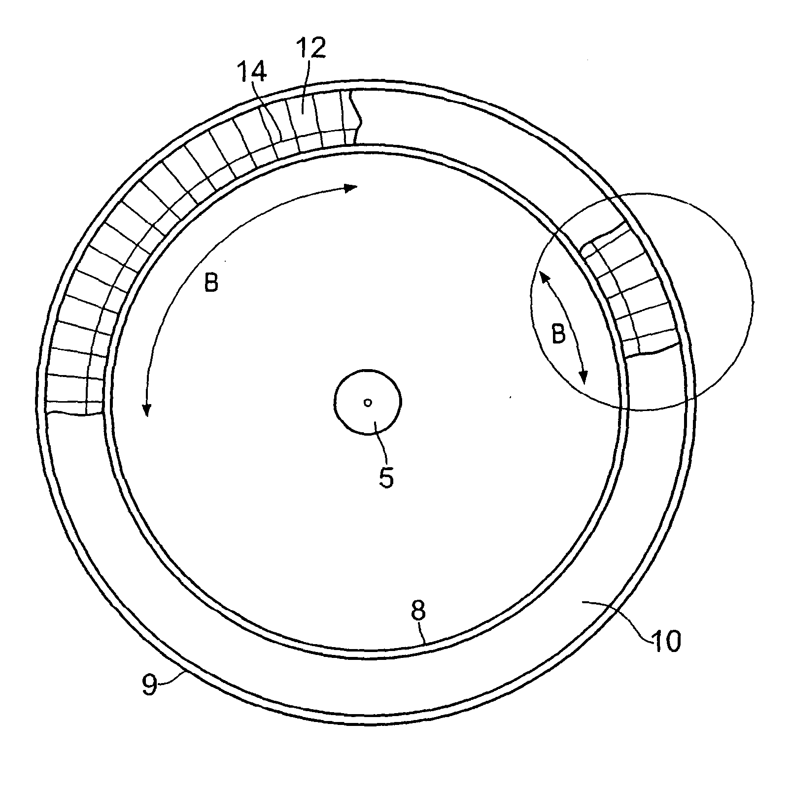
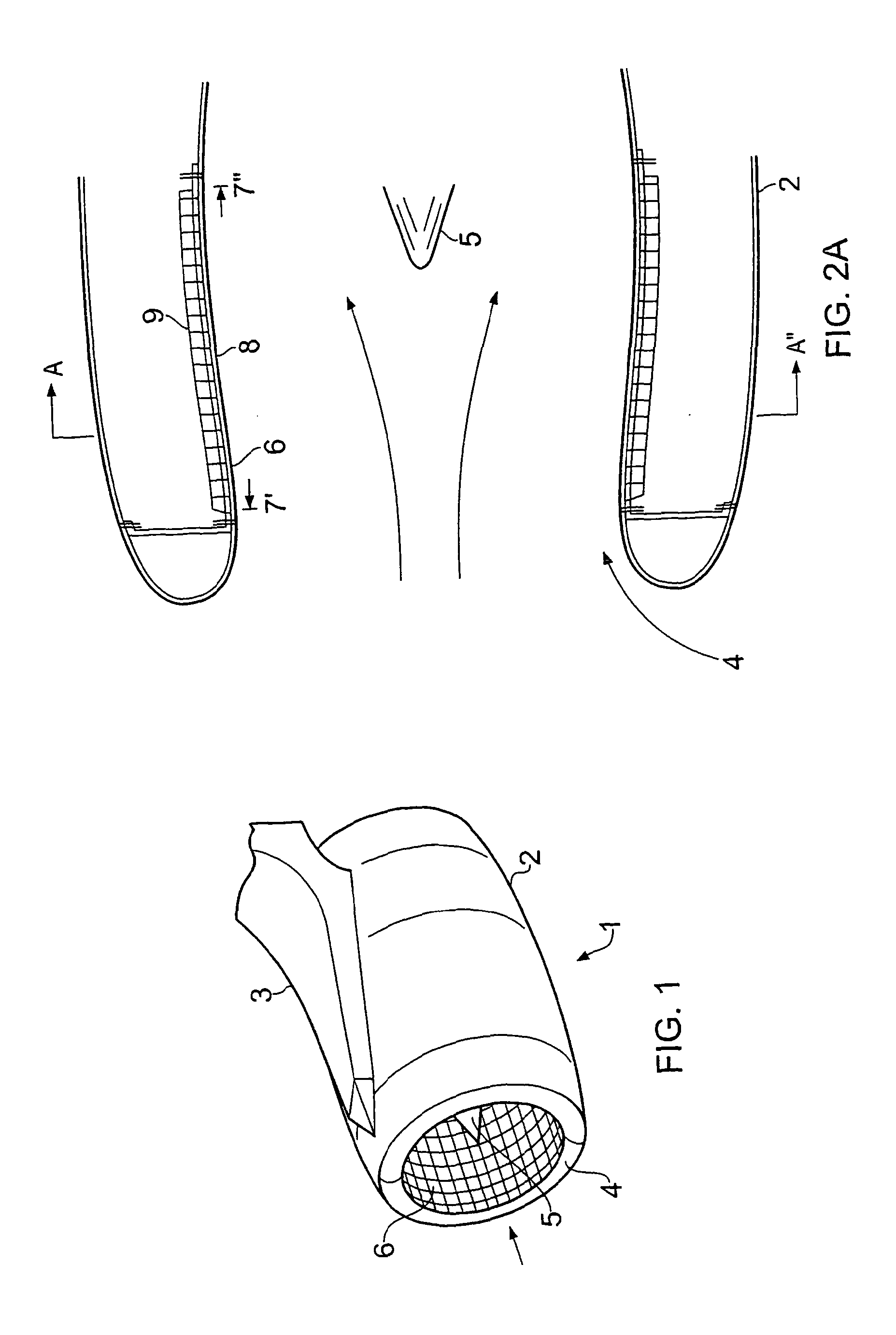
[0128]FIG. 1 shows a typical turbofan engine 1 comprising an engine outer casing 2 and a pylori 3 connecting the engine to the aircraft wing or fuselage (not shown).

[0129]The engine comprises an air inlet passage 4 extending into the engine and towards the fan blades (not shown) of the engine. The blades are mounted on a rotatable shaft 5 which can be seen in the centre of the inlet passage 4.

[0130]Rotation of the fan blades causes undesirable high noise levels to be emitted from the front of the engine. Consequently, and as illustrated in FIG. 1, in order to reduce the noise output from the engine an acoustic liner 6 is arranged within the air inlet up-stream of the fan blades. Noise emitted from the blades in a frontward direction, which would otherwise be reflected from the passage surfaces, can thus be attenuated by the liner 6.

[0131]It can be seen from FIG. 1 that the liner shape corresponds to the inlet passage of the engine but can be generally described as a ‘barrel’ or cyli...


PUM

PropertyMeasurementUnit
atmospheric pressureaaaaaaaaaa
pressureaaaaaaaaaa

Abstract

The invention relates to a method of manufacturing a composite acoustic panel employed in an inlet passage of a gas turbine engine (1). The acoustic panel comprises a permeable face-layer (8), an impermeable backing sheet (9) and a sound absorbing layer (10) disposed therebetween. The method comprises a double polymerisation process for the face-layer and the remainder of the acoustic panel and finally a perforation step to perforate the face-layer according to a pre-determined perforation distribution (11.1, 11.2, 11.3, 11.4, 11.5).

Description

FIELD OF THE INVENTION[0001]The present invention relates to an acoustic liner arrangement particularly, but not exclusively, for use in a gas turbine or turbofan engines of the type fitted to commercial aircraft or the like. The invention extends to a method of manufacturing the same.BACKGROUND[0002]Noise levels generated by modern commercial aircraft during take-off and landing are of significant importance to aircraft operators. In order to reduce (to attenuate) the noise emitted by aircraft engines, the air intake passages of gas turbine or turbofan engines are generally provided with acoustic liners on the inner surfaces of the engine which are configured to attenuate the noise generated by the engine in operation.[0003]Various designs of noise attenuating panel are known in the art. Generally, the panels comprise a perforated layer defining part of the inlet passage of the engine and a further imperforate layer defining the back of the panel. A honeycomb layer, such as that ma...

Claims


Application Information

Patent Timeline
Patent Type & Authority Applications(United States)
IPC IPC(8): F02K1/82B26D3/08
CPCB29C70/088Y10T156/1057B29C70/443B29C70/545B29C70/865B29C70/88B29K2105/04B29K2105/243B29K2995/0001B29L2031/608B64D33/02B64D2033/0206B64D2033/0286F02C7/045G10K11/172Y02T50/672B26D3/08F02K1/827F05D2260/96F05D2250/283B23B39/16B23B2215/04B23B2226/27B29C70/32Y10T83/02Y02T50/60B32B3/12B32B5/18B32B5/26B32B37/146B32B38/04B32B2038/047B32B2305/024B32B2305/022B32B2305/076B32B2605/18B29C70/446
Inventor VAVALLE, ARMANDO
Owner GKN AEROSPACE SERVICES LTD
Why Eureka
Try Eureka