
Microbially-based sensors for environmental monitoring

a microorganism and environmental monitoring technology, applied in the field of environmental monitoring, can solve the problems of significant environmental and human health challenges, high nitrate loss from agricultural land managed by subsurface or tile drainage systems, and pollution from agricultural production and other sources, and achieve the effects of low cost, accurate and durabl

Active Publication Date: 2013-03-28
CAMBRIAN INNOVATION
View PDF2 Cites 18 Cited by
  • Summary
  • Abstract
  • Description
  • Claims
  • Application Information

AI Technical Summary

Benefits of technology

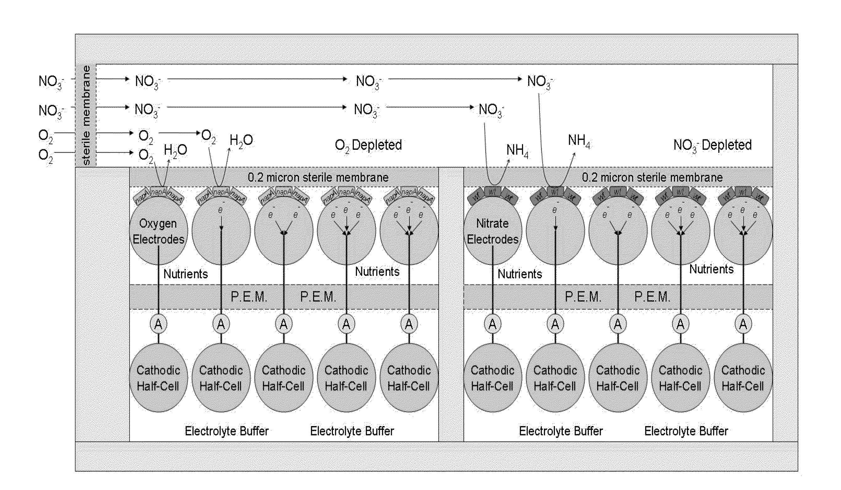
The present invention introduces low-cost, real-time biodoctor devices for environmental monitoring, specifically surface water monitoring. These devices are made based on the activity of electricity-generating microbes, providing an affordable, durable, and accurate tool for monitoring agencies, research institutions, and farmers. This technology is useful for monitoring and controlling nutrient run-off over large areas.

Problems solved by technology

Surface water nitrate (NO3) pollution from agricultural production and other sources is a well-established problem in the United States.
The widespread nitrate contamination of waterways across the country has led to significant environmental and human health challenges.
It has been found that nitrate loss from agricultural land managed by subsurface or tile drainage systems is particularly high (Dinnes, et al., 2002).
However, there are a number of disadvantages which are halting their widespread utilization, such as generally high cost and short lifetime or labor intensive maintenance, with some specific issues regarding sensing range and precision.
This cost is due to their complicated design and features (self-calibration, auto-cleaning, pressure-resistant casings, spectrophotometer equipment) which makes them difficult and expensive to fix if broken.
However, they have several drawbacks which make them less applicable in critical environments.
Their main limitation is sensitivity to temperature and a severe interference by ionic compounds.
This leads to one of the most limiting factors for widespread use: their poor performance in marine environments.
As described, existing methods for monitoring nitrate levels in surface water through periodic field monitoring and sample are labor and materials intensive, expensive (between $500 to $15,000 dollars per sensor, depending on the technology) and short-lived (average time to replace ˜6 month, depending on the technology).
Moreover, given the mobility of nitrogen, the current monitoring practices give an incomplete picture of ongoing nitrate loss.

Method used


Image

  • Microbially-based sensors for environmental monitoring
  • Microbially-based sensors for environmental monitoring
  • Microbially-based sensors for environmental monitoring

Examples


example 1

Development of a Microbially-Based Nitrate Sensor

[0073]The present example demonstrates the feasibility of using the preferential electron acceptor utilization of Shewanella oneidensis as the basis for a microbial sensor. Specifically, the present example aims to:[0074]1) Demonstrate differential current down a concentration gradient of oxygen established by diffusion and respiratory consumption[0075]2) Demonstrate differential current down a concentration gradient of nitrate established by diffusion and respiratory consumption.[0076]3) Establish preliminary sensor design based on the parameters of sensor dimensions, consumption rate of electron acceptor, and diffusivity of the electron acceptor species.

The sensor is developed in four parallel steps according to the method outlined below.

Step 1: Construct the Test Cells

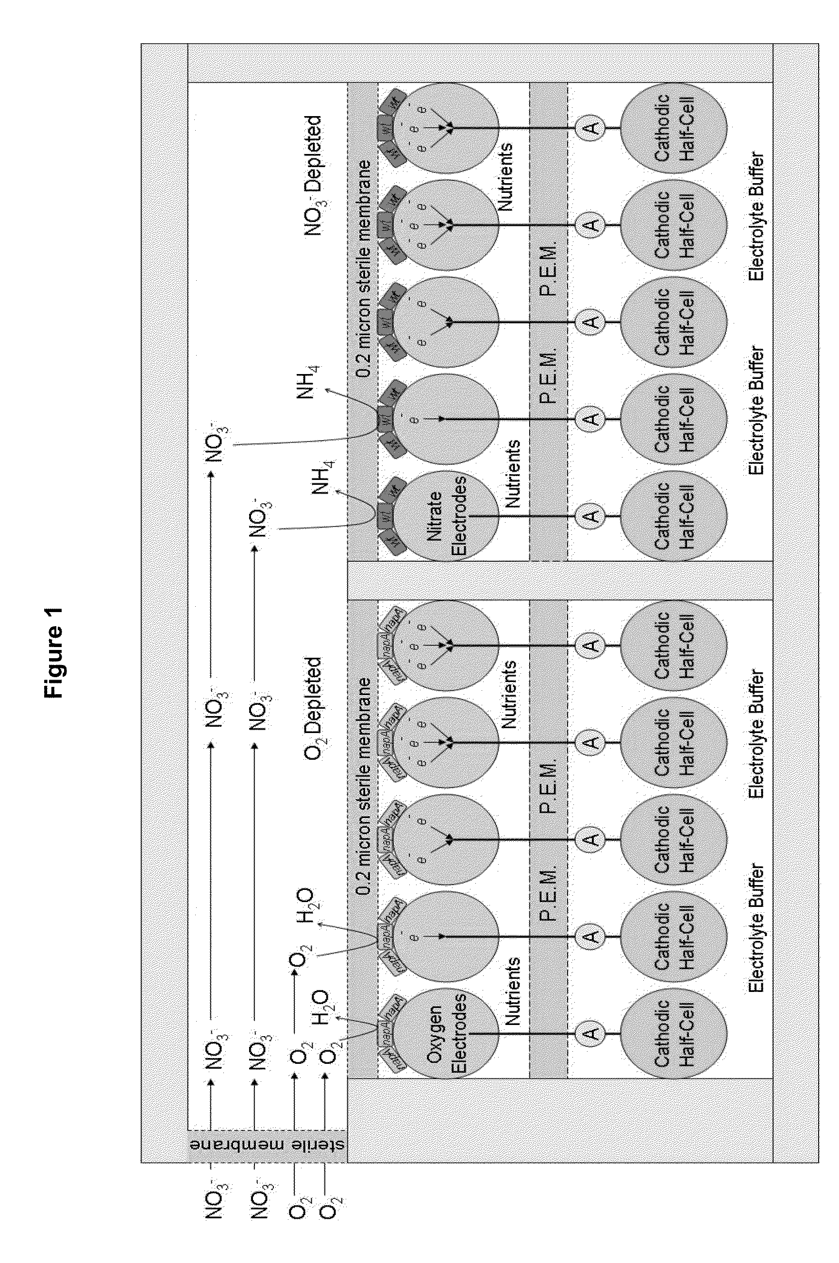
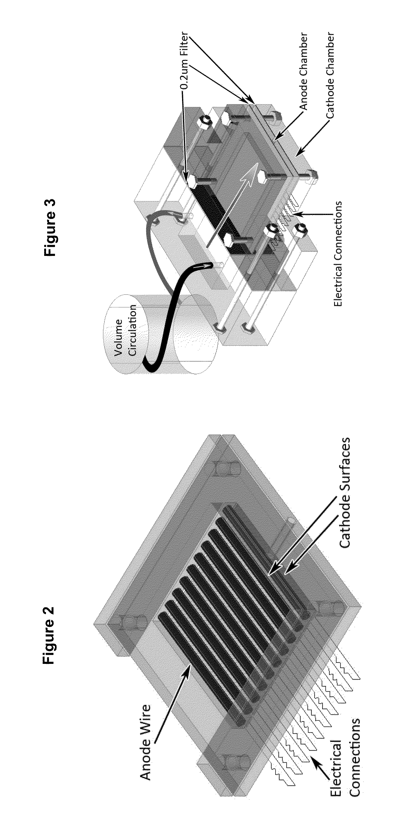
[0077]The test cells for Phase I is composed of two components, the sensor region and the media recirculation system (FIG. 2). The general design of these components ...


PUM

PropertyMeasurementUnit
Volumeaaaaaaaaaa
Currentaaaaaaaaaa
Permeabilityaaaaaaaaaa

Abstract

The present invention relates to the field of surface water monitoring. More specifically, the present invention provides low-cost, real-time bio-electrochemical sensors for surface water monitoring based on the metabolism of one or more electrogenic microbes.

Description

CROSS-REFERENCE TO RELATED APPLICATIONS[0001]This application claims priority to U.S. Provisional Patent Application No. 61 / 267,594, filed Dec. 8, 2009, and to International Application Serial No. PCT / US2010 / 025224, filed Feb. 24, 2010. The contents of each of these applications are hereby incorporated by reference in their entireties.FIELD OF THE INVENTION[0002]The present invention relates to the field of environmental monitoring, and in particular to the development bio-electrochemical sensors for monitoring chemical compound levels in surface water.BACKGROUND OF THE INVENTION[0003]Surface water nitrate (NO3) pollution from agricultural production and other sources is a well-established problem in the United States. For example, nitrate levels in the Mississippi River have more than doubled since 1965 and have increased 3 to 10-fold in the northeastern U.S. since 1990 (Vitousek et al, 1997). The widespread nitrate contamination of waterways across the country has led to significa...

Claims


Application Information

Patent Timeline
IPC IPC(8): G01N27/327
CPCG01N33/1866G01N27/327G01N33/0054C12Q1/02G01N33/0037G01N33/0044G01N33/182Y02E60/50G01N27/404G01N27/4168
Inventor BUCK, JUSTINSILVER, MATTHEW
Owner CAMBRIAN INNOVATION
Learn More