Vehicle drag reduction assembly

a technology for reducing aerodynamic drag and vehicle bodies, applied in vehicle arrangements, roofs, transportation and packaging, etc., can solve the problems of increasing shipping costs, reducing fuel economy, and affecting the safety of passengers,

Inactive Publication Date: 2013-03-28
ISB LLC
View PDF4 Cites 17 Cited by
  • Summary
  • Abstract
  • Description
  • Claims
  • Application Information

AI Technical Summary

Benefits of technology

[0011]The following presents a simplified summary of the invention in order to provide a basic understanding of some aspects of the invention. This summary is not an extensive overview of the invention. It is not intended to identi...

Problems solved by technology

It is well-known that aerodynamic drag on vehicle bodies has a number of undesirable effects, including a reduction in fuel economy.
In addition to environmental concerns, rising fuel prices contribute to increases in shipping costs that must be passed along to the public.
Rigid structures can maintain their shape against air currents, but have the disadvantage of adding weight and complexity to the loading/unloading process (e.g., the panels must be swung to the side to open the trailer).
Rigid structures are also easily bent or otherwise damaged (e.g., rigid side skirts are often deformed if the trailer is pulled across a mound such as railroad tracks).
In addition, devices that create the greatest reduction in aerodynamic drag require complex surface curves, which are expensive to manufacture, so most such devices use less efficient ...

Method used


Image

  • Vehicle drag reduction assembly
  • Vehicle drag reduction assembly
  • Vehicle drag reduction assembly

Examples


Embodiment Construction

[0051]It is to be understood by one of ordinary skill in the art that the present discussion is a description of exemplary embodiments only, and is not intended as limiting the broader aspects of the present invention, which broader aspects are embodied in the exemplary constructions.

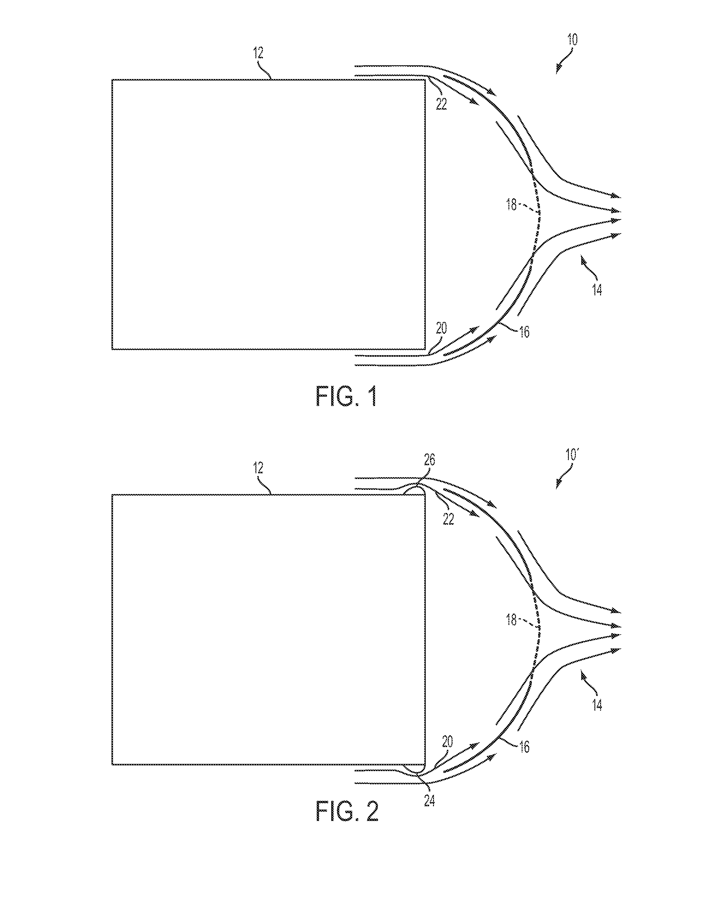
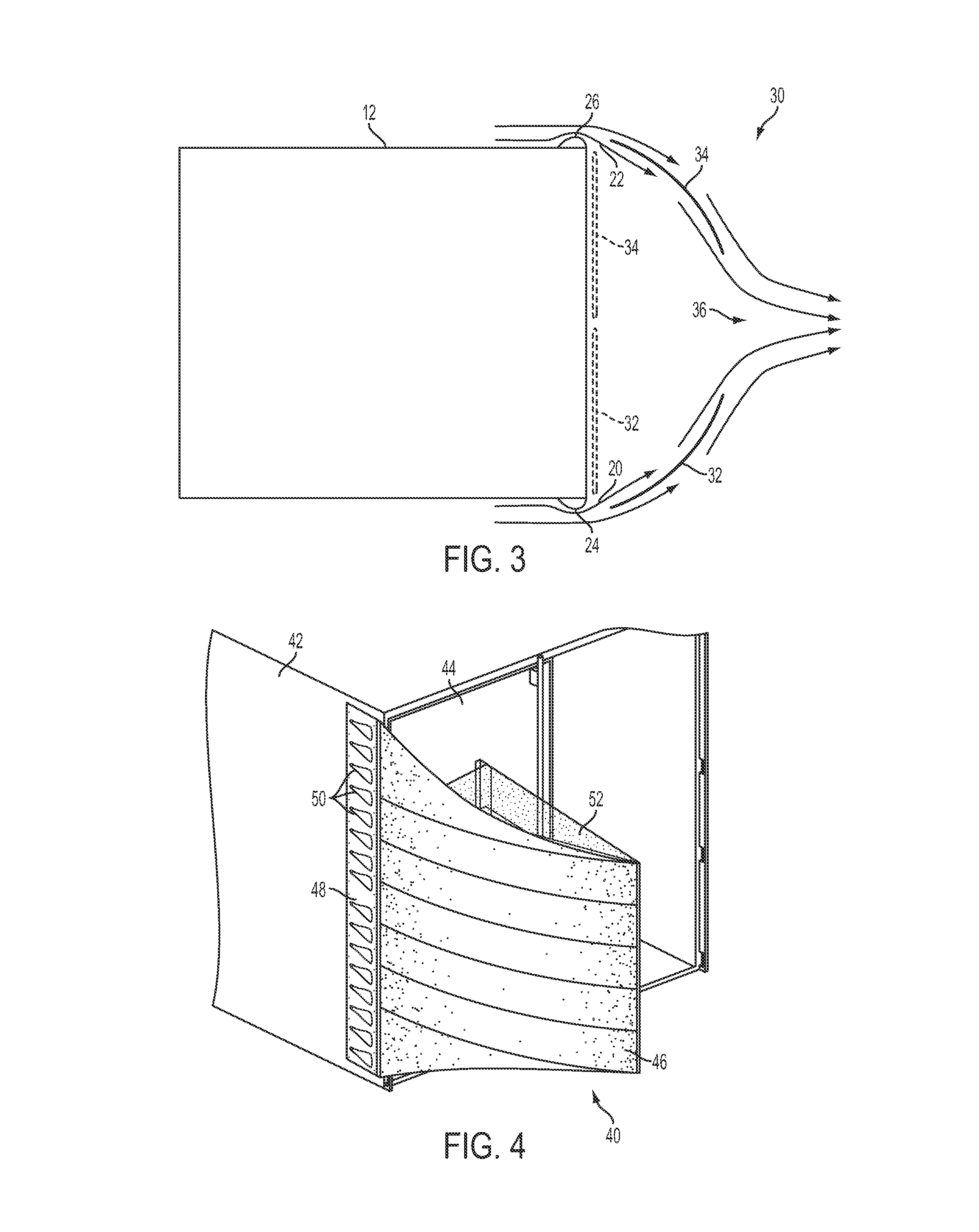
[0052]By way of additional background, those skilled in the art are aware that any solid object in relative motion to the surrounding fluid environment will experience forces applied by that fluid. The forces exerted by the fluid comprise viscous friction of the fluid in laminar flow combined with mass effects of turbulent flow. In most cases of severe aerodynamic drag, the primary adverse force is from the turbulent effects. Thus, altering the shape of an object to promote laminar flow, and retard or prevent the boundary separation to turbulent flow, will reduce the adverse forces, especially in a gaseous environment.

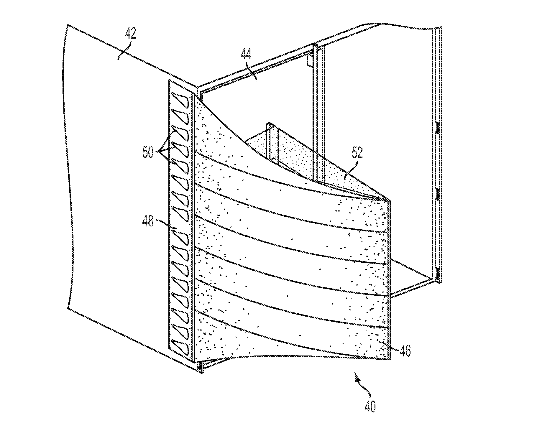
[0053]It is well known that adding a device to the boxy shape of a semi-trailer can sm...


PUM


Abstract

A drag reduction assembly is mountable on a vehicle or other object experiencing relative motion in a fluid environment. The assembly comprises at least one shell of flexible web material movable between non-deployed and deployed positions. In addition, the shell is configured to provide at least an outer flow surface in the deployed position (e.g., a curved surface) to reduce the effects of aerodynamic drag. In many embodiments, intake apertures such as NACA ducts may be provided to allow a portion of the flowing fluid into the shell. The flowing fluid will cause the shell to assume automatically the deployed position. In cases where fluid enters the shell, an exit location is provided in the shell to permit such fluid to exit and rejoin fluid on the outside.

Description

PRIORITY CLAIM[0001]This application is based upon and claims priority to U.S. provisional application Ser. No. 61 / 538,202, filed Sep. 23, 2011, and U.S. provisional application Ser. No. 61 / 691,291, filed Aug. 21, 2012, both of which are incorporated fully herein by reference for all purposes.BACKGROUND OF THE INVENTION[0002]This invention relates to the reduction of aerodynamic drag on vehicles such as tractor-trailers, as well as other objects that experience relative motion with respect to surrounding fluid.[0003]It is well-known that aerodynamic drag on vehicle bodies has a number of undesirable effects, including a reduction in fuel economy. These effects are particularly acute in the case of semi-trailers and intermodal containers, which have a box-like shape. In addition to environmental concerns, rising fuel prices contribute to increases in shipping costs that must be passed along to the public.[0004]There have been efforts in the prior art to provide drag reducing devices ...

Claims


Application Information

Patent Timeline
IPC IPC(8): B62D35/00
CPCB62D35/004B62D35/001
Inventor WAYBURN, LEWIS S.TUEL, STEPHEN M.
Owner ISB LLC
Why Eureka
Try Eureka