
Tank dewatering sensing and valve control method and apparatus

a technology of sensing valve and dewatering method, which is applied in the direction of filtration separation, borehole/well accessories, separation process, etc., can solve the problems of complex fittings of density sensors, high cost of recovering oil from containment area, and reliability and accuracy of such a dewatering method

Inactive Publication Date: 2013-04-04
SAUDI ARABIAN OIL CO
View PDF5 Cites 14 Cited by
  • Summary
  • Abstract
  • Description
  • Claims
  • Application Information

AI Technical Summary

Benefits of technology

The present invention provides a method and apparatus for detecting the transition of liquid from water to oil in a pipe. This is achieved by measuring various properties of the liquid flow, such as sound pressure level, electrical conductivity, and vibration, and comparing them to predetermined threshold values. The invention can detect the water to oil transition at a specific point in the pipe and can also determine if the liquid is flowing in a laminar or turbulent manner. The technical effects of the invention include improved detection of water to oil transition, improved accuracy, and improved reliability.

Problems solved by technology

However, recovering the oil from the containment area is an expensive exercise.
The reliability and accuracy of such a dewatering method is subject to the diligence of the operators.
However, density sensors such as those discussed above are not suitable for use with any liquid of unpredictable or erosive nature which can damage the tines causing erratic results.
Further, such density sensors require complicated fitting within a pipe in order to perform the sampling.
Still further such density sensors are prone to fouling when sampling particularly viscous liquids such as crude oil.

Method used


Image

  • Tank dewatering sensing and valve control method and apparatus
  • Tank dewatering sensing and valve control method and apparatus
  • Tank dewatering sensing and valve control method and apparatus

Examples


Embodiment Construction

[0061]It is to be noted that the discussions contained in the “Background” section and that above relating to prior art arrangements relate to discussions of documents or devices which form public knowledge through their respective publication and / or use. Such should not be interpreted as a representation by the present inventor(s) or patent applicant that such documents or devices in any way form part of the common general knowledge in the art. References will be made later herein to Appendix A, B and C where:

[0062]Appendix A is a table showing kinematic viscosity of water and crude oil,

[0063]Appendix B is a table showing conductivity information for water and crude oil, and

[0064]Appendix C is a table showing density information for water and crude oil.

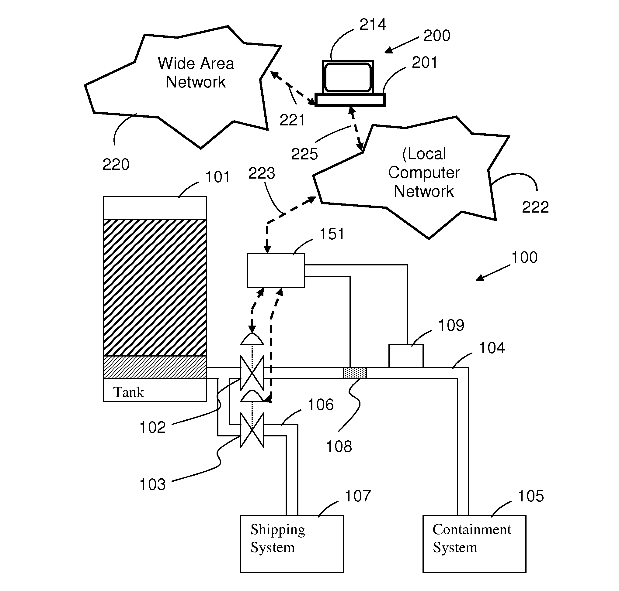
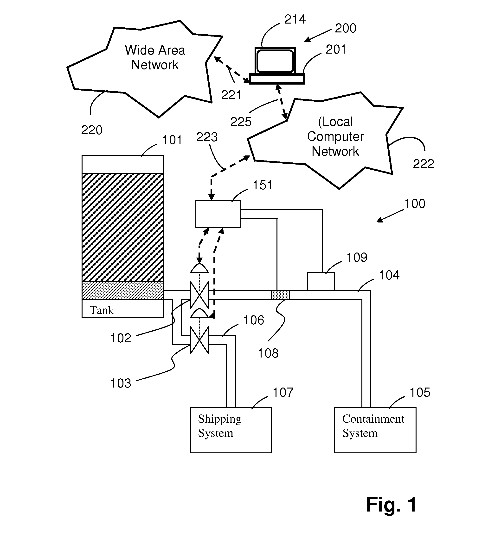
[0065]FIG. 1 shows a system 100 for dewatering a bulk-storage tank 101. The system 100 comprises two motorised valves 102 and 103. The valve 102 controls flow of liquid through a pipe 104 connecting the base of the tank 101 to a cont...


PUM

PropertyMeasurementUnit
diameteraaaaaaaaaa
kinematic viscosityaaaaaaaaaa
frequencyaaaaaaaaaa

Abstract

A system for separating water from crude oil includes a bulk-storage tank for storing unrefined crude oil, a first pipe for delivering water separated from crude oil in the bulk-storage tank to a containment system, a second pipe for delivering crude oil to a shipping system, a first valve for controlling flow in the first pipe, a second valve for controlling flow in the second pipe, and a control system for controlling operation of the first and second valves. The control system has a control device for controlling the first and second valves, an acoustic sensor array mounted on the first pipe for sensing a sound pressure level during flow of water through the first pipe, means for comparing the sensed sound pressure level with a predetermined sound pressure threshold level characterizing flow of oil-water mixture through the pipe, and a control device for closing the first valve and opening the second valve when the measured sound pressure level reaches the sound pressure threshold level.

Description

RELATED APPLICATIONS[0001]This application claims the benefit of priority to U.S. Provisional Patent Application No. 61 / 541,713 filed Sep. 30, 2011, the disclosure of which is incorporated herein by reference in its entirety.FIELD OF THE INVENTION[0002]The present invention relates generally to dewatering a bulk-storage tank and, in particular, to a method and apparatus for detecting water-to-crude oil transition in a pipe.BACKGROUND[0003]Unrefined crude oil stored in a bulk-storage tank has a percentage of water entrained within the oil. Such crude oil is typically pumped into a bulk-storage tank prior to shipment. The capacity of bulk-storage tanks vary, but may be one-hundred (100) million barrels (i.e., 15.9 giga-litres). Over a period of twenty-four (24) to forty-eight (48) hours, the water and oil stored in a tank separate naturally, with the water collecting at the bottom of the tank beneath the oil. The separated water and the crude oil within the tank are very distinct exce...

Claims


Application Information

Patent Timeline
Patent Type & Authority Applications(United States)
IPC IPC(8): B01D35/14
CPCB01D17/0214C10G33/08E21B43/34B01D17/12B01D17/0208
Inventor AL-MULHIM, KHALID ABDULAZIZAL-QAHTANI, SALEM MOHAMMED
Owner SAUDI ARABIAN OIL CO
Learn More