Welding jig and welding process for planar magnetic components

a planar magnetic and welding jig technology, applied in the field of welding, can solve the problems of reducing the speed of the production line, reducing the operating space, and time-consuming manual soldering using the soldering iron, and achieving the effect of eliminating quality problems and saving time and labor costs

Active Publication Date: 2013-04-04
DELTA ELECTRONICS INC
View PDF12 Cites 5 Cited by
  • Summary
  • Abstract
  • Description
  • Claims
  • Application Information

AI Technical Summary

Benefits of technology

[0036]As described above, the welding jig and welding process for soldering the PIN pins and PIN needles of the planar magnetic component of the invention can save time and labor costs. Moreover, the planar magnetic component fabricated by soldering the PIN pins and PIN needles of the planar magnetic component using the welding jig and welding process can also eliminate quality problems in the follow-up process of the planar magnetic component encountered in the prior art as a result of solder cracks generated during the cutting of the PIN needles.

Problems solved by technology

1) Manual soldering using the soldering iron is time-consuming, and only a small operating space is provided for this operation.
2) Manual soldering using the soldering iron is performed only on one end of each PIN pin at a time. This reduces the speed of the production line.
3) Manual soldering is performed by a human which increases labor costs.
4) During the cutting of the PIN needles, the solder on the PWB may crack. This may be the source of quality problems in follow-up processes.

Method used


Image

  • Welding jig and welding process for planar magnetic components
  • Welding jig and welding process for planar magnetic components
  • Welding jig and welding process for planar magnetic components

Examples


Embodiment Construction

[0046]The invention will be described in the following embodiments with reference to the accompanying drawings. However, the embodiments are not intended to limit the invention. Moreover, it is not intended for the description of operation to limit the order of implementation. Any device with equivalent functions that is produced from a structure formed by a recombination of elements shall fall within the scope of the invention. In addition, the drawings are only illustrative and are not drawn to the original size.

[0047]The terminology “about,”“approximately” or “substantially” in this specification generally refers to an error or range of a value within 20%, preferably within 10% and more preferably within 5%. If not specifically explained, the value is regarded as an approximate value, i.e., within an error or range covered by “about,”“approximately” or “substantially.”

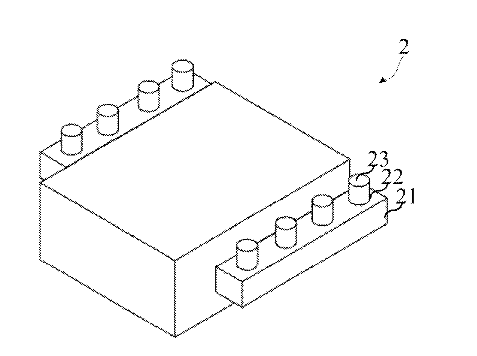
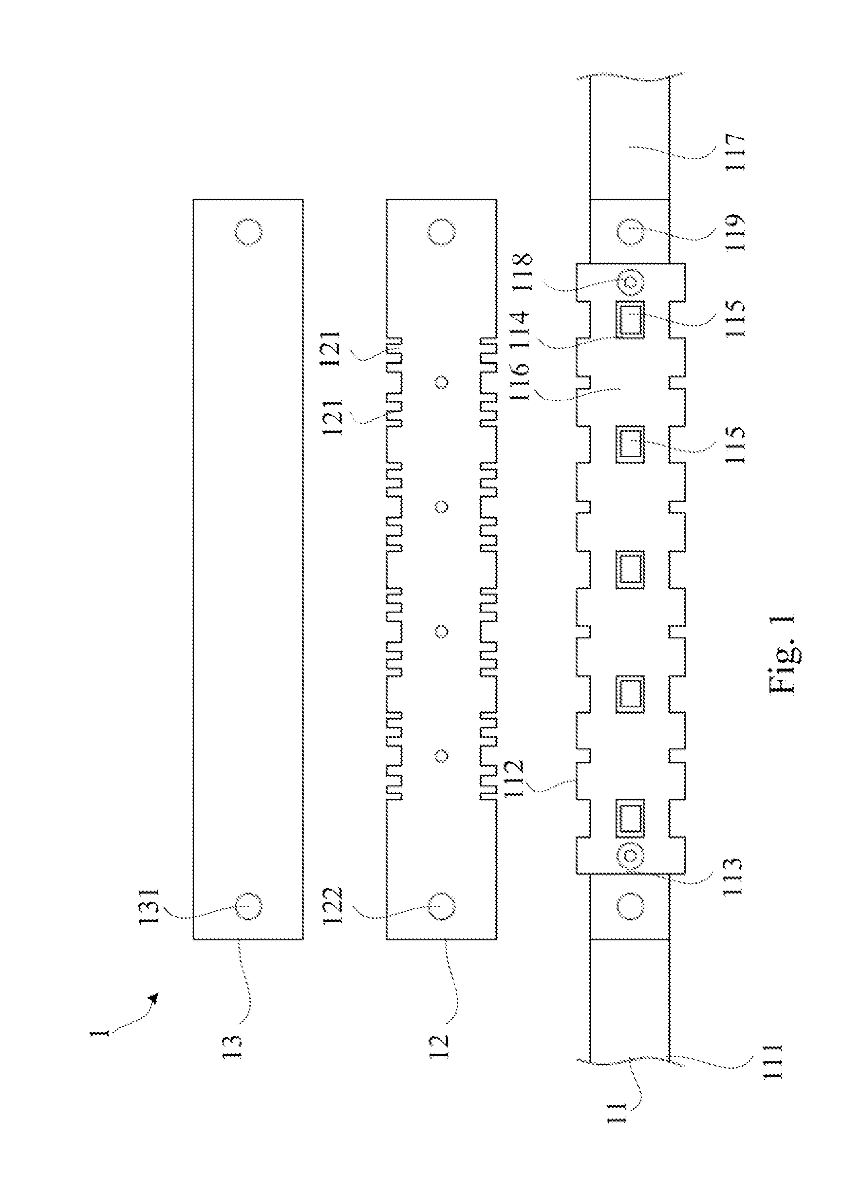
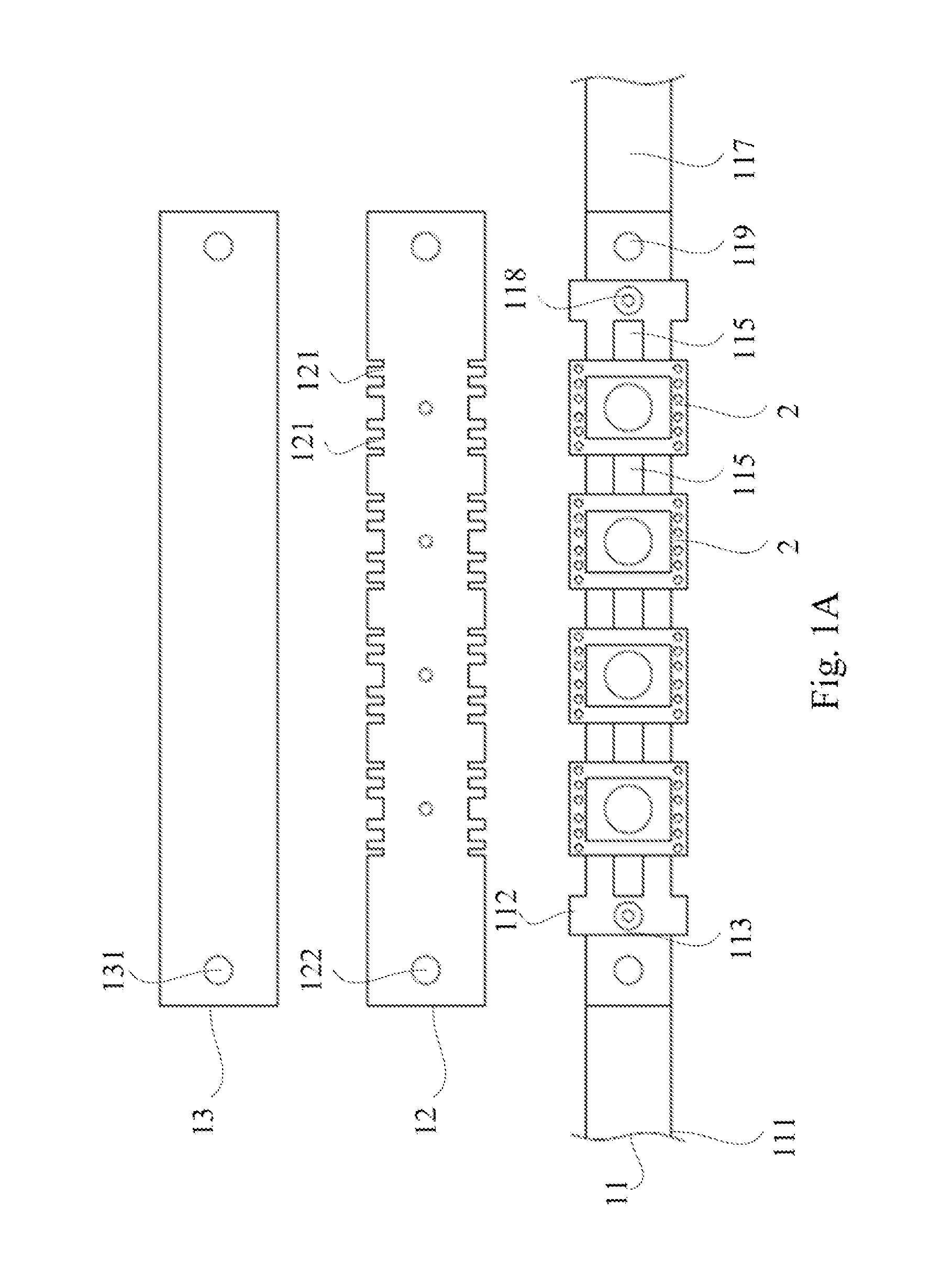
[0048]FIG. 1 is an exploded view of a welding jig according to an embodiment of the invention, and FIGS. 1A to 1C...


PUM

PropertyMeasurementUnit
timeaaaaaaaaaa
timeaaaaaaaaaa
timeaaaaaaaaaa

Abstract

A welding jig and welding process for planar magnetic components are provided. The welding jig includes a fixed piece and an elastic piece. The fixed piece includes a base and a carrier. The base has an opening, bumps at the bottom of the opening and a pair of operation ends extending from the opening. The carrier is fixed on the base and located in the opening, and has multiple through holes. When the bumps are located respectively in the through holes, an accommodation interval is formed between adjacent pairs of the bumps for the placement of the planar magnetic components. The elastic piece is secured to the fixed piece, and when the planar magnetic components are placed in the accommodation intervals of the fixed piece, the elastic piece covers the planar magnetic components and the planar magnetic components abut against two side edges of the elastic piece.

Description

RELATED APPLICATIONS[0001]This application claims priority to Chinese Application Serial Number 201110295912.2, filed Sep. 30, 2011, which is herein incorporated by reference.BACKGROUND[0002]1. Field of Invention[0003]The invention relates to welding. More particularly, the invention relates to a novel welding jig and welding process for planar magnetic components.[0004]2. Description of Related Art[0005]Compared with the traditional transformer, a planar magnetic component, such as a planar transformer, employs a material such as a single layer or multilayer printed wiring board (PWB) or copper foil to replace copper wires found in the traditional transformer. The wires in the planar transformer actually are planar conductors, and the current tends to flow at the edges far away from the center but totally passes through the conductor, so that a high current density can be obtained. In addition, the magnetic core applied in the planar transformer has a small volume, large area and f...

Claims


Application Information

Patent Timeline
Patent Type & Authority Applications(United States)
IPC IPC(8): B21J13/08C21D1/40
CPCB23K1/0016B23K2201/38B23K37/0408B23K3/087B23K2101/38
Inventor HSIEH, CHUNG-KUANGGUO, LANFAN, KAO-KUANTENG, HUI-HUA
Owner DELTA ELECTRONICS INC
Why Eureka
Try Eureka