
Wireless Power Receiving Unit For Receiving Power, A Wireless Power Transferring Unit For Transferring Power, A Wireless Power Transferring Device And Use Of Wireless Power Transferring Device

a wireless power transmission and wireless power technology, applied in electric vehicle charging technology, charging stations, transportation and packaging, etc., can solve the problems of unoptimized energy transfer efficiency between the power transferring unit and the power receiving unit, affecting the efficiency of power transferring and receiving, and ferromagnetic materials, etc., to and improve power transferring efficiency

Active Publication Date: 2013-04-04
ABB E-MOBILITY BV
View PDF9 Cites 4 Cited by
  • Summary
  • Abstract
  • Description
  • Claims
  • Application Information

AI Technical Summary

Benefits of technology

The present invention provides a wireless power receiving unit with improved power receiving efficiency, a wireless power transferring unit with improved power transferring efficiency, and a wireless power transferring device with improved power transferring and receiving efficiency. The invention also limits the spread of the alternating magnetic field to the surrounding environment. The receiving concentrator core is positioned in the vicinity of the induction coil and is adapted to concentrate the magnetic field and enhance the magnetic coupling between the power transferring unit and the power receiving unit. The receiving guide member abuts the receiving concentrator core and provides a transition for the magnetic field between the medium and the receiving concentrator core, improving the efficiency of the power receiving unit. The magnetic permeability of the receiving guide member is decreasing from the inner part to the outer part, improving the transition for the magnetic field from the medium to the receiving concentrator core.

Problems solved by technology

A problem with wireless power transferring devices is that ferromagnetic materials, such as a steel body of a vehicle, in vicinity of the device is subjected to the alternating magnetic field, wherein the material is heated up due to eddy currents.
Accordingly, the energy transfer efficiency between the power transferring unit and the power receiving unit is not optimal.
Furthermore, it is important to limit the spread of the alternating magnetic field to the surrounding environment since high flux of the alternating magnetic field could have biological impact on people and animals.

Method used


Image

  • Wireless Power Receiving Unit For Receiving Power, A Wireless Power Transferring Unit For Transferring Power, A Wireless Power Transferring Device And Use Of Wireless Power Transferring Device
  • Wireless Power Receiving Unit For Receiving Power, A Wireless Power Transferring Unit For Transferring Power, A Wireless Power Transferring Device And Use Of Wireless Power Transferring Device
  • Wireless Power Receiving Unit For Receiving Power, A Wireless Power Transferring Unit For Transferring Power, A Wireless Power Transferring Device And Use Of Wireless Power Transferring Device

Examples


Embodiment Construction

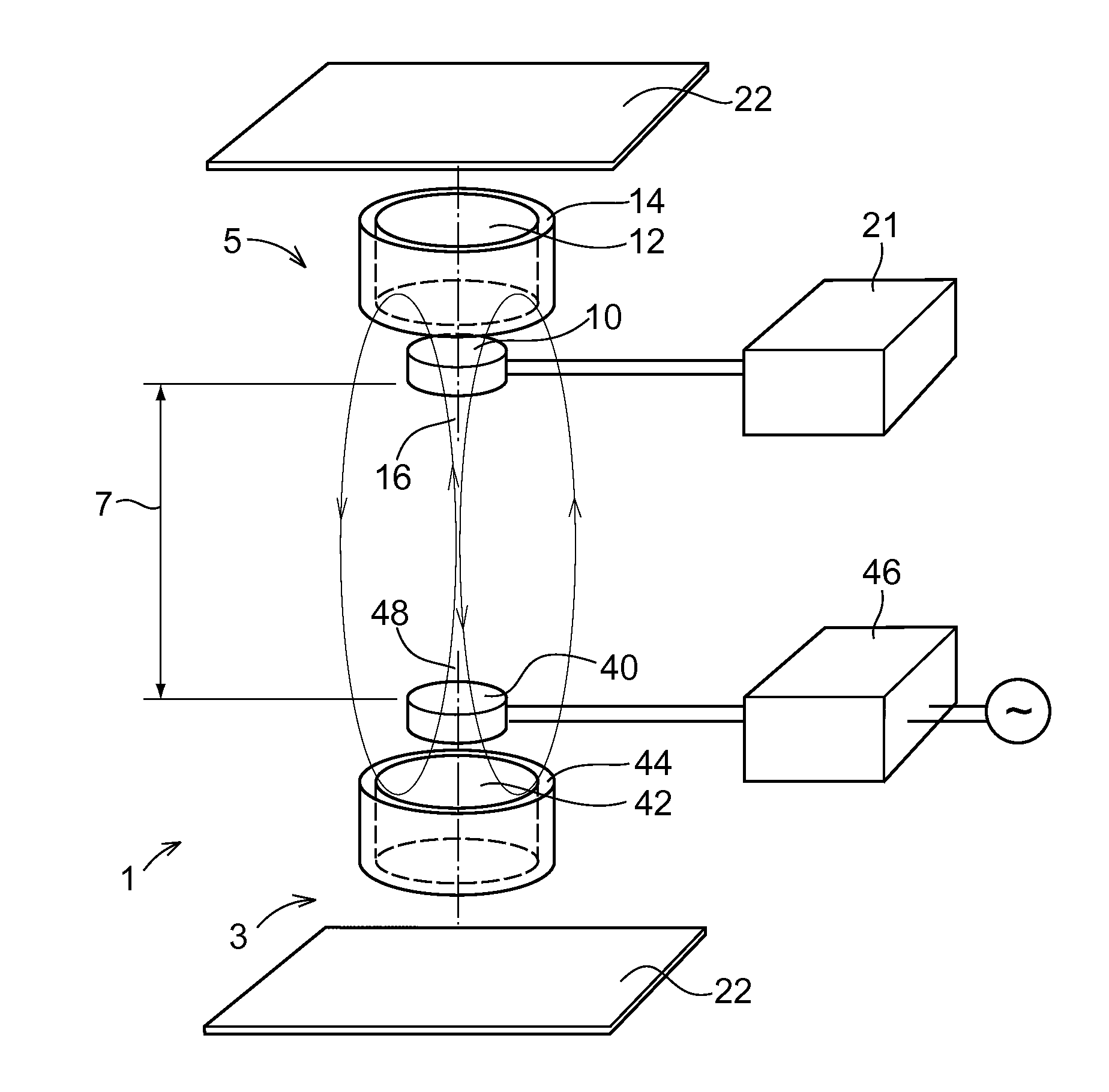
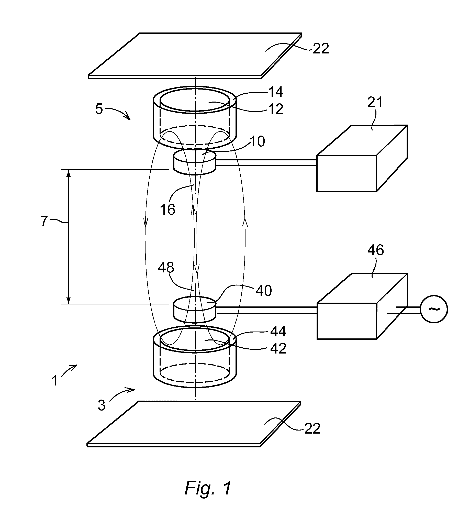
[0055]FIG. 1 shows a wireless power transferring device 1 comprising a wireless power transferring unit 3 and a wireless power receiving unit 5. The wireless power transferring device 1 is adapted to transfer power from the power transferring unit 3 to the power receiving unit 5. The power transferring unit 3 and the power receiving unit 5 is separated by an air gap 7.

[0056]The power transferring device 1 is adapted to transfer power to a vehicle, wherein the power transferring unit 3 is located at the ground and the power receiving unit 5 is located at a lower part of the vehicle.

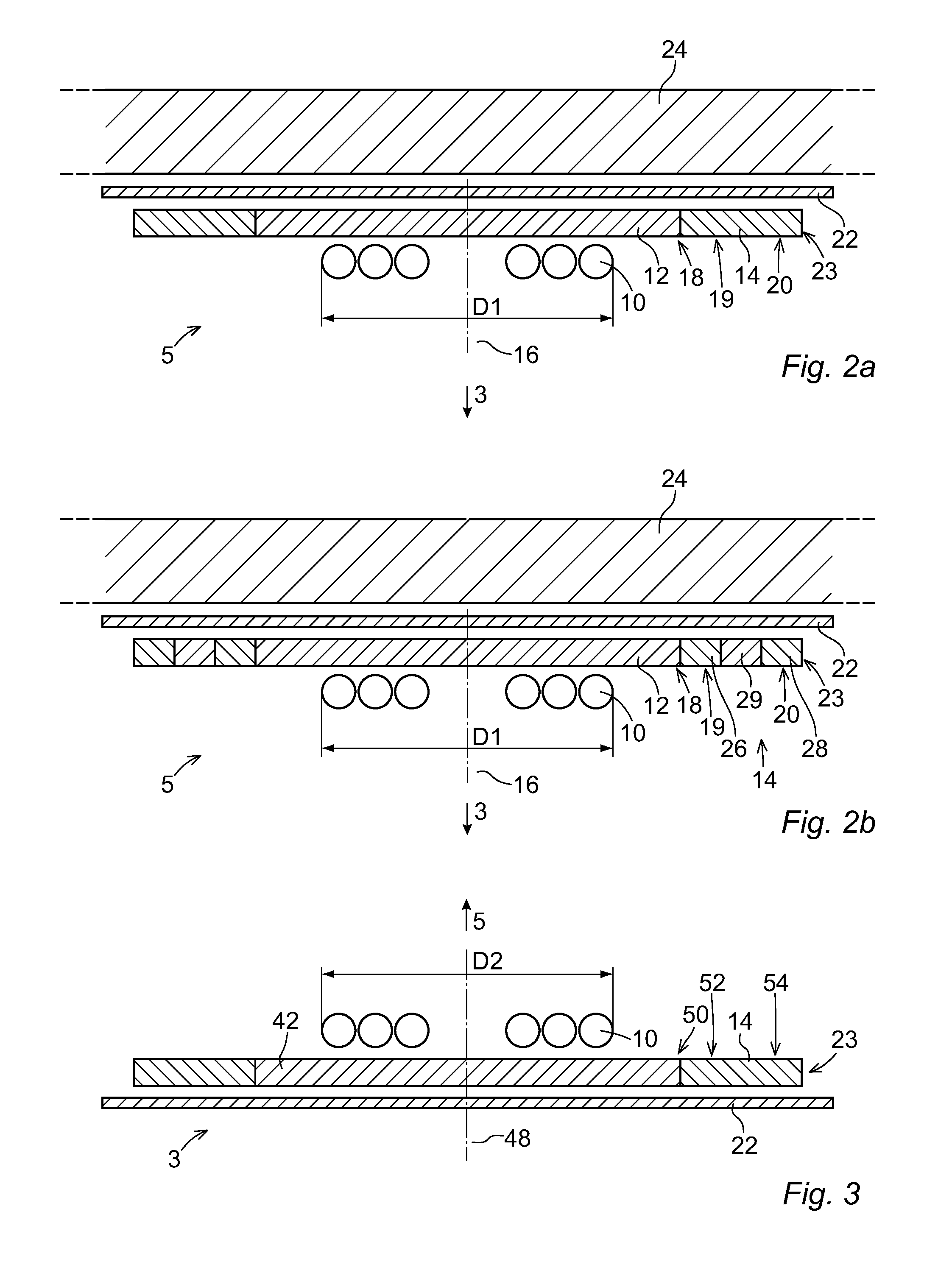
[0057]The wireless power receiving unit 5 is adapted to receive power from the power transferring unit 3. The wireless power receiving unit 5 comprises an induction coil 10, a receiving concentrator core 12, and a receiving guide member 14.

[0058]The induction coil 10 is adapted to be subjected to power in the form of an alternating magnetic field from the power transferring unit 3. Thereby an alternating c...


PUM

PropertyMeasurementUnit
frequencyaaaaaaaaaa
frequencyaaaaaaaaaa
resonance frequencyaaaaaaaaaa

Abstract

A wireless power transferring device, a wireless power transferring unit and a wireless power receiving unit for transferring and receiving power. The power receiving unit includes an induction coil adapted to be subjected to an alternating magnetic field so that an alternating current is induced in the induction coil, a receiving concentrator core adapted to concentrate the magnetic field wherein the receiving concentrator core is surrounded by a medium, and a receiving guide member arranged to provide a smooth transition for the magnetic field between the medium and the concentrator core, and abutting the receiving concentrator core. The receiving guide member has a magnetic permeability in the range between the magnetic permeability of the receiving concentrator core and the medium.

Description

FIELD OF THE INVENTION[0001]The present invention generally relates to a wireless power receiving unit for receiving power and a wireless power transferring unit for transferring power.[0002]The present invention also generally relates to a wireless power transferring device, which power transferring device comprises a wireless power transferring unit and a wireless power receiving unit, and use of the wireless power transferring device.BACKGROUND OF THE INVENTION[0003]Wireless power transferring devices, such as Inductively Coupled Power Transfer systems (ICPT), are used for transferring power from a power transferring unit to a power receiving unit. Wireless power transferring devices are for example used for charging battery units of an electric vehicle.[0004]The power transferring unit is adapted to generate an alternating magnetic field of high frequency. The magnetic field couples the power transferring unit to the power receiving unit over a gap with a medium. The gap is ofte...

Claims


Application Information

Patent Timeline
Patent Type & Authority Applications(United States)
IPC IPC(8): H01F38/14
CPCB60L11/182H01F27/36H01F38/14H02J5/005H02J7/025H04B5/0037Y02T10/7088Y02T90/122Y02T90/14H04B5/0075Y02T10/7005B60L53/122H02J50/70H02J50/10H01F27/363Y02T10/70Y02T10/7072H04B5/24H04B5/79Y02T90/12
Inventor TENGNER, TOMAS
Owner ABB E-MOBILITY BV
Learn More