Touch sensor, and controller provided with the touch sensor

a technology of touch sensor and controller, which is applied in the field of touch sensors, can solve the problems of inability to increase the resolution of the touch sensor as desired, the difficulty of manipulating all of the parameters through mouse operation alone, and the inability to increase the number of electrodes formed on the fader sensor. achieve the effect of improving the detection resolution

Inactive Publication Date: 2013-04-04
YAMAHA CORP
View PDF3 Cites 26 Cited by
  • Summary
  • Abstract
  • Description
  • Claims
  • Application Information

AI Technical Summary

Benefits of technology

[0015]In view of the foregoing prior art problems, it is an object of the present invention to provide an improved touch sensor which is provided on a

Problems solved by technology

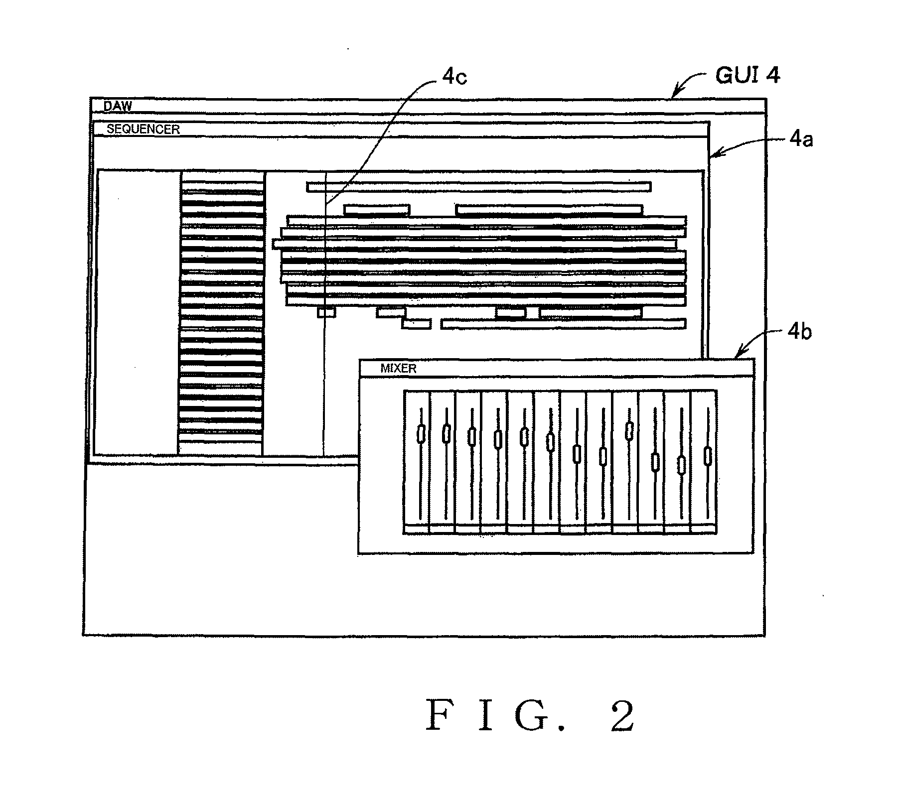
Further, the number of functions performed by the DAW software and hence parameters therefor has been increasing, so that it is difficult to manipulate all of the parameters through operation of a mouse alone.
However, because the controller is of a small size, each of the fader sensors too has to be small in size, so that the number of electrodes formed on the fader sensor cannot be increased as desired.
As a consequence, there would be encountered the problem that the resolution of the touch sensors cannot be increased as desired.
However, the aforementioned conventionally-known operator devices would present the following problems.
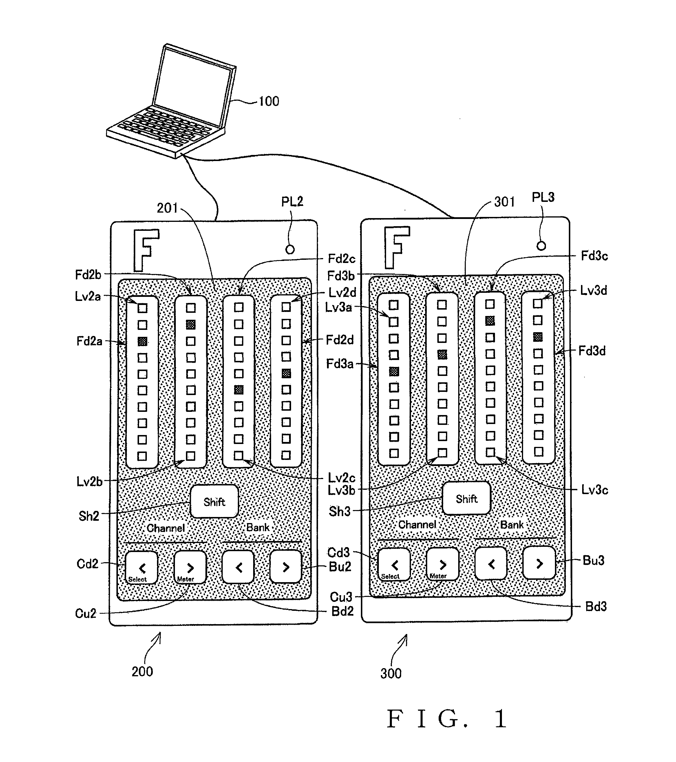
Because the display elements (light emitting elements) are provided on a side of the operating section in spaced relation to the operator section, it would be difficult for an operation feeling, with which the user operates the operator section, and display positions of the display elements to intuitively match each other, and thus,

Method used


Image

  • Touch sensor, and controller provided with the touch sensor
  • Touch sensor, and controller provided with the touch sensor
  • Touch sensor, and controller provided with the touch sensor

Examples


second embodiment

of the Controller

[0101]FIG. 12 is a perspective view showing an outer appearance of a music piece data input device 1 which is an embodiment of the controller of the present invention, and FIG. 13 is an exploded perspective view showing component parts of the music piece data input device 1. The music piece data input device 1 comprises, among others: an exterior casing 10 including an upper case 11 and a lower case 15; a circuit substrate (first circuit substrate) 20 provided within the exterior casing 10; a switch type controller 30 provided on the circuit substrate 20 within the exterior casing 10; and a fader type controller 40. Details of these component parts will be discussed hereinbelow.

[0102]The upper case 11 and the lower case 15 are each a flat plate member of a generally rectangular shape having peripheral walls (outer peripheral edge portions) formed of synthetic resin or the like. The outer peripheral edge portions 15a of the lower case 15 are bent upwardly, while the ...

third embodiment

of the Controller

[0164]The following describe a third embodiment of the controller of the present invention. Note that, in the following description and corresponding drawings related to the third embodiment, similar elements to those in the second embodiment are indicated by the same reference numerals and characters as used for the second embodiment and will not be described here to avoid unnecessary duplication. Further, in the third embodiment, the other features than those to be described hereinbelow are the same as in the second embodiment, FIG. 21 is an exploded perspective view of a third embodiment of the music piece data input device 1-2 of the present invention.

[0165]The embodiment of the music piece data input device 1-2 does not include the fader type controller 40 provided in the second embodiment of the music piece data input device, but it includes, in the place of the fader type controller 40 on the circuit substrate 20 in the second embodiment, additional pad type ...


PUM


Abstract

One electrode and another electrode adjoining an upper end region of the one electrode in an operating direction of a fader sensor are divided by a boundary line extending zigzag in a generally M shape transversely relative to the operating direction, so that upper and lower apex portions of the one electrode and the other electrode bite into each other. Similarly, the one electrode and another electrode adjoining a lower end region of the one electrode each other are divided by a boundary line extending zigzag in a generally M shape transversely relative to the operating direction. As a finger touches the fader sensor, the finger simultaneously touches the three electrodes, and corresponding output signals are output therefrom. A weighted average of the output signals is calculated so that position information of the finger having touched the sensor can be acquired with a high resolution.

Description

BACKGROUND[0001]The present invention relates generally to touch sensors, such as faders or sliders, for detecting a user-operated position in a one-dimensional operating direction, and more particularly to a touch sensor applicable to controllers for manipulating or setting a parameter related to audio signal processing or any of other various signal processing.[0002]The present invention also relates to an improvement of display structures in fader controllers provided with a touch sensor.[0003]In the field of audio signal processing apparatus using a computer, it has heretofore been known to perform audio processing, such as recording, editing, mixing, etc. of performance data, through digital signal processing. The computer used in such audio signal processing apparatus is a general-purpose computer like a PC (Personal Computer), which includes various hardware devices, such as an audio interface and MIDI (Musical Instrument Digital Interface) interface. Further, the computer ha...

Claims


Application Information

Patent Timeline
IPC IPC(8): G06F3/041
CPCG06F3/041G06F3/0213G06F3/0362G06F3/044G06F2203/04104G06F3/0416G06F3/041661G06F3/0443
Inventor TANAKA, HISANORIOCHI, MITSUNORIKAMIHARA, MASANORIKOGA, RYOHEISHIMIZU, TSUNEOENDO, JUNJI
Owner YAMAHA CORP
Why Eureka
Try Eureka