Mold having release layer for imprinting, method for producing mold having release layer for imprinting, and method for producing copy mold

a technology of imprinting and release layer, which is applied in the field of molds, can solve the problems of conventional techniques facing the limit of densification, the magnetic influence between adjacent recording tracks or recording bits is no longer ignored, and the density of the magnetic medium has been further increased, etc., and achieves the effect of ensuring the quality of the mold

Inactive Publication Date: 2013-04-04
HOYA CORP
View PDF1 Cites 7 Cited by
  • Summary
  • Abstract
  • Description
  • Claims
  • Application Information

AI Technical Summary

Benefits of technology

[0040]According to the present invention, a sufficient mold releasability is provided at a lower releasing pressure and a material to be patterned is favorably filled in a pattern on a mold. Thus, the pattern can be accurately, stably, and repeatedly transferred.

Problems solved by technology

Meanwhile, the density of the magnetic medium has been further increased and the magnetical influence between the adjacent recording tracks or recording bits is no longer ignorable.
Thus, the conventional technique is facing the limit of densification.
Furthermore, a large number of copy molds (working replicas) need to be produced by repeating the above described steps.

Method used


Image

  • Mold having release layer for imprinting, method for producing mold having release layer for imprinting, and method for producing copy mold
  • Mold having release layer for imprinting, method for producing mold having release layer for imprinting, and method for producing copy mold
  • Mold having release layer for imprinting, method for producing mold having release layer for imprinting, and method for producing copy mold

Examples


first embodiment

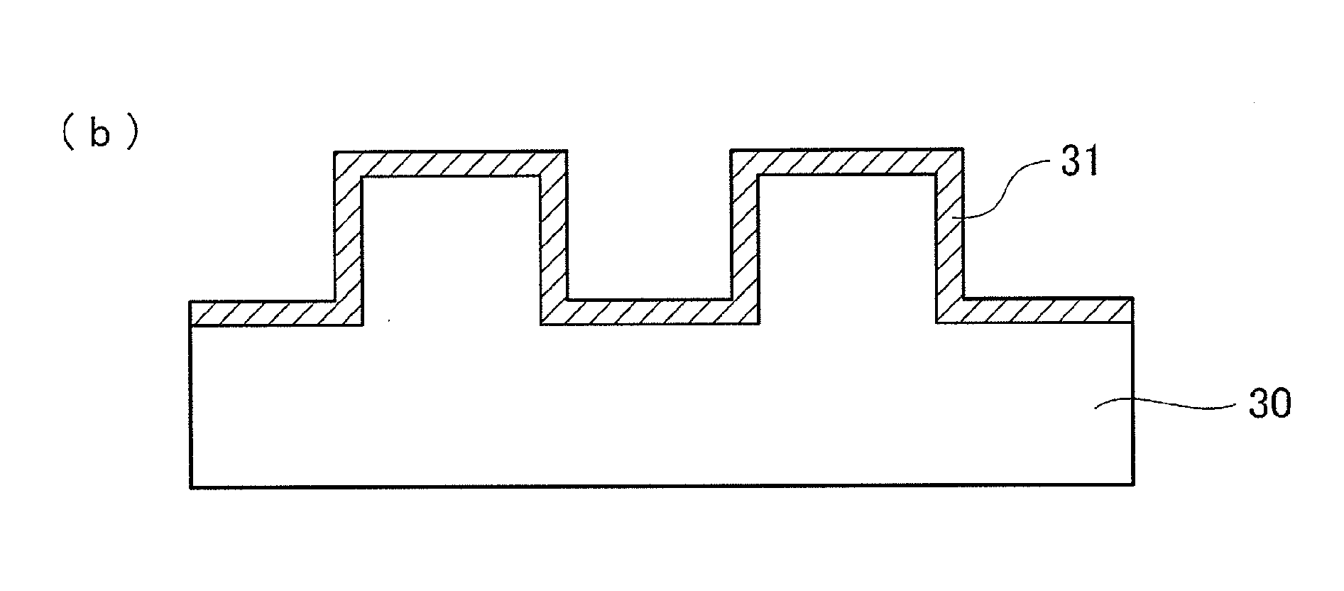
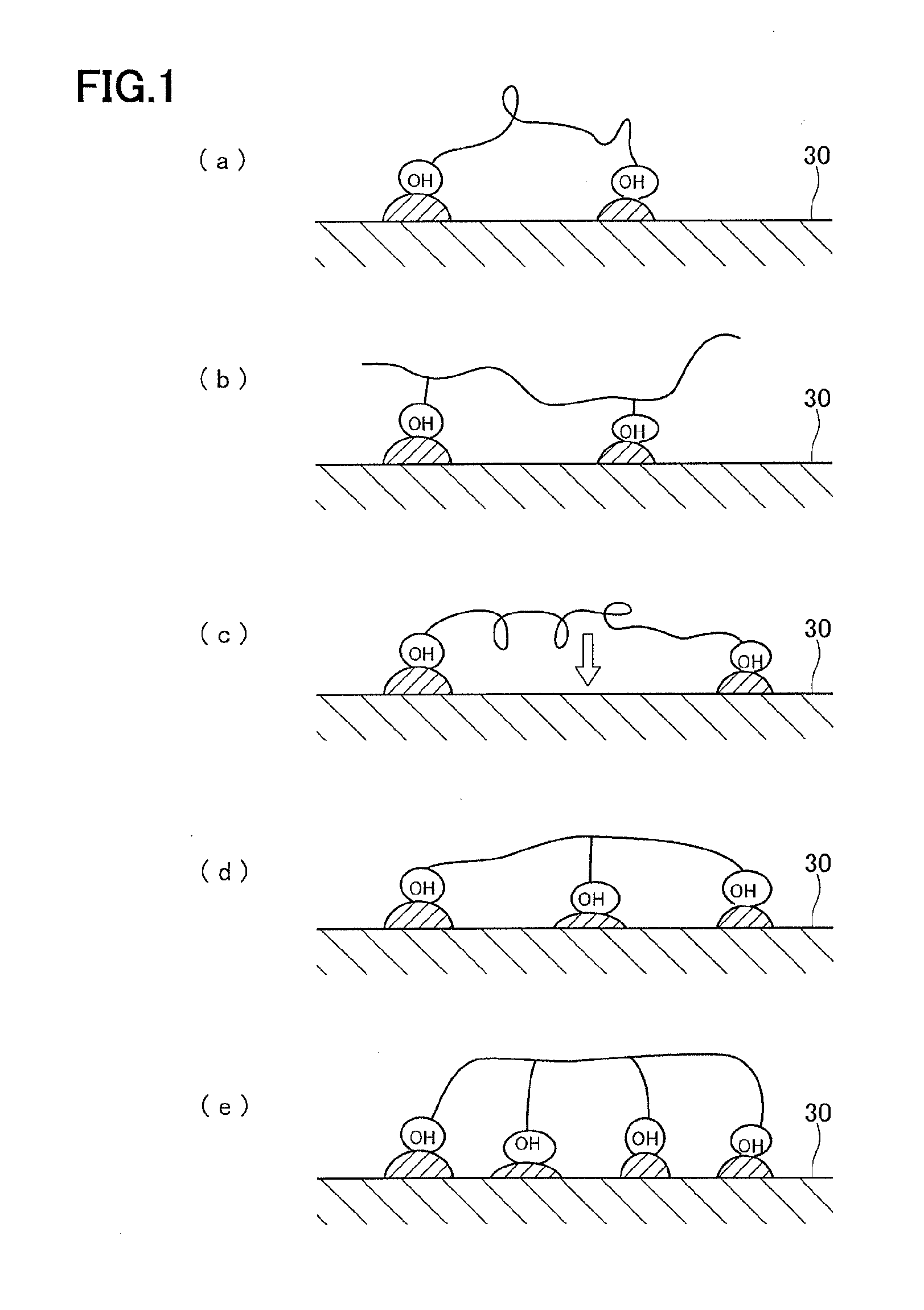
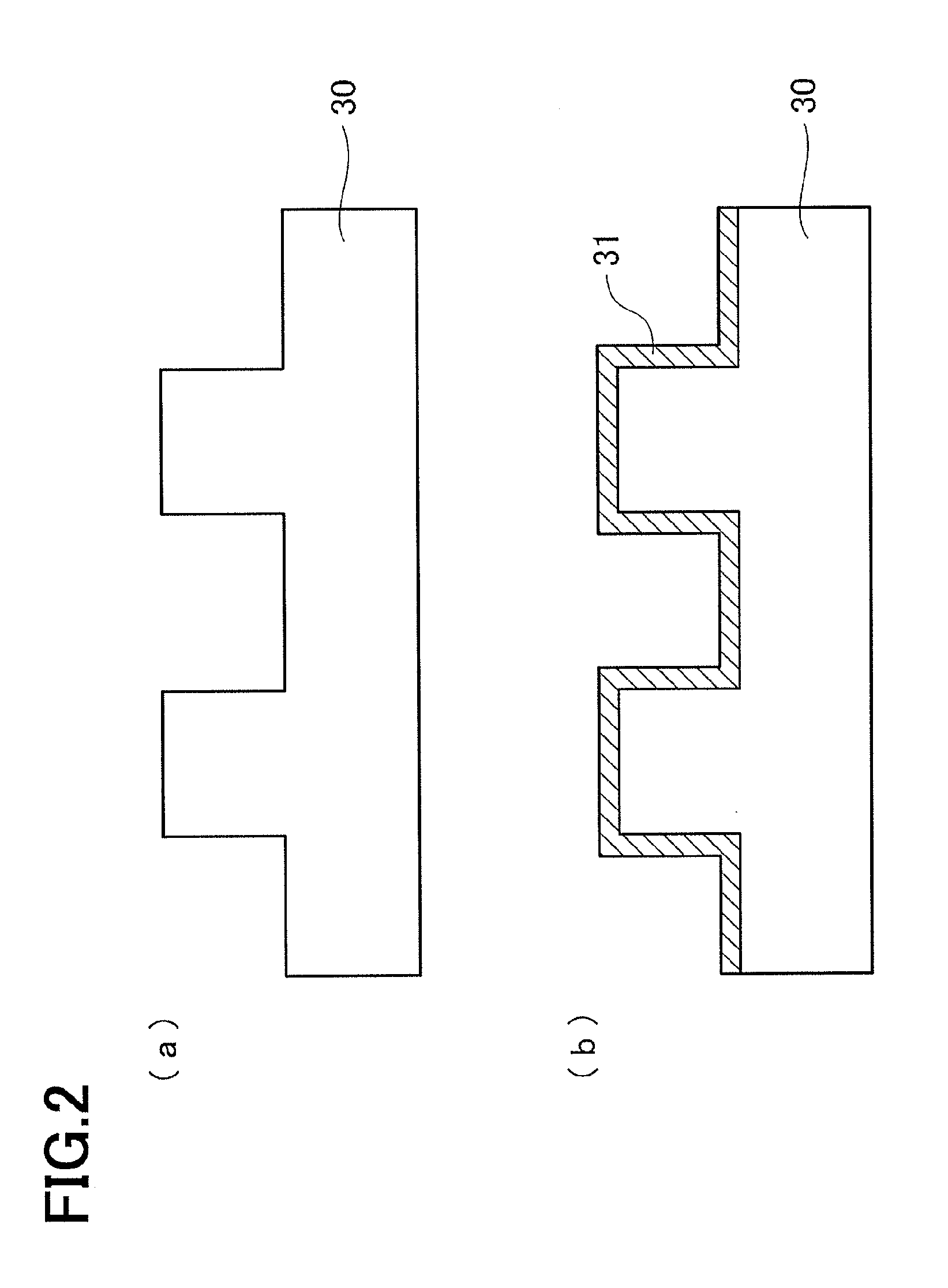
[0057]An embodiment of the present invention is described below. The description is given in the following order. First, a step of disposing a release layer on a mold is described with reference to FIG. 2, which is a schematic cross-sectional view. Then, a step of producing a copy mold 20 from a master mold as an original by optical nanoimprint technology is described with reference to FIG. 3, which is a schematic cross-sectional view.

[0058]It is a matter of course that, in a case where a pattern is transferred using the copy mold, the copy mold may be provided with the release layer. In the embodiment, the mold includes the master mold for imprinting and a primary copy mold reproduced by transferring using the master mold, as well as a higher copy mold including a secondary mold, a third mold, and so on reproduced thereafter.

[0059](Preparing Mold)

[0060]First of all, a mold 30 that serves an original pattern for an uneven pattern to be transferred onto a copy mold 20 is prepared as ...

second embodiment

[0156]In the first embodiment described above, the copy mold 20 to be produced from the master mold for optical imprinting is described.

[0157]On the other hand, in this embodiment, the copy mold 20 to be produced from a master mold for thermal imprinting will be described. Note that portions not particularly mentioned in the following description are similar to those in the first embodiment.

[0158]To begin with, as a substrate used for producing the copy mold 20 from the master mold for thermal imprinting, a SiC substrate can be used. The SiC substrate has resistance against chlorine gas used in dry etching on the hard mask layer 7.

[0159]Other than the SiC substrate having resistance against chlorine gas, a silicon wafer that has a relatively low resistance against the chlorine gas can also be used for the substrate 1 for thermal imprinting, by giving the following treatment. Namely, a SiO2 layer is first disposed on the silicone wafer 1. Then, the hard mask layer 7 is disposed on th...

example

[0174]In this example, a mold 30 formed of a quartz substrate having a periodic structure with a depth of 30 nm, a depth at the recess (groove) of 15 nm, a depth at the protrusion (protruding portion) of 35 nm, and a pitch of 50 nm.

[0175]The mold 30 is dipped in a release agent compound for 5 minutes. The release agent compound includes the following compound (molecular weight of (C3F6O)n is equal to or larger than 500 and equal to or smaller than 6000) diluted to 0.5 wt % with VERTREL XF-UP (manufactured by Du Pont-Mitsui Fluorochemicals Co., Ltd, VERTREL is a registered trade mark).

[0176]Then, the mold 30 was pulled out from the solution of the release agent compound at a speed of 120 mm / min. The release agent compound was coated on through such a dip method.

[0177]Here, a plurality of samples were prepared and were each subjected to the heating at a temperature of 25 to 205 after being pulled out. Then, the mold 30 was rinsed. The rinsing was performed by 10 minutes dipping again ...


PUM

PropertyMeasurementUnit
temperatureaaaaaaaaaa
widthaaaaaaaaaa

Abstract

Provided is a mold having a release layer, in which the release layer is disposed in the mold which transfers a specific uneven pattern onto a molding material to be patterned by means of an imprinting method, wherein the main chain of the molecular chains of a compound contained in the release layer contains a fluorocarbons, the molecular chains of the compound have at least two adsorption functional groups that are adsorbed or bonded to the mold, the bonding energy in the adsorption functional groups that becomes the source of adsorption or bonding of the adsorption functional groups to the mold is greater than the bonding energy between one adsorption functional group and another adsorption functional group in the molecular chains of the compound, and the surface free energy of the release layer is optimized by means of heating.

Description

TECHNICAL FIELD[0001]The present invention relates to a mold having a release layer for imprinting, a method for producing the mold having the release layer for imprinting, and a method for producing a copy mold.BACKGROUND ART[0002]Conventionally, regarding a magnetic medium used for a hard disc and the like, there has been used a method in which magnetic particles are made into infinitesimals, the width of a magnetic head is minimized, and the width between data tracks on which information is recorded is narrowed, so as to achieve a high recording density.[0003]Meanwhile, the density of the magnetic medium has been further increased and the magnetical influence between the adjacent recording tracks or recording bits is no longer ignorable. Thus, the conventional technique is facing the limit of densification.[0004]In recent years, a magnetic medium called a patterned medium has been proposed. In the patterned medium, the adjacent recording tracks or recording bits are magnetically ...

Claims


Application Information

Patent Timeline
Patent Type & Authority Applications(United States)
IPC IPC(8): B29C59/00
CPCB29C59/002G03F7/0002B82Y40/00B82Y10/00B29C33/62B29C33/58B29C33/56B29C33/60B29C33/3807H01L21/0273B29C2033/385
Inventor SUZUKI, KOTAKOBAYASHI, HIDEO
Owner HOYA CORP
Why Eureka
Try Eureka