
Real-time physiological signal measurement and feedback system

Inactive Publication Date: 2013-04-04
NAT TAIWAN UNIV OF SCI & TECH
View PDF16 Cites 32 Cited by
  • Summary
  • Abstract
  • Description
  • Claims
  • Application Information

AI Technical Summary

Benefits of technology

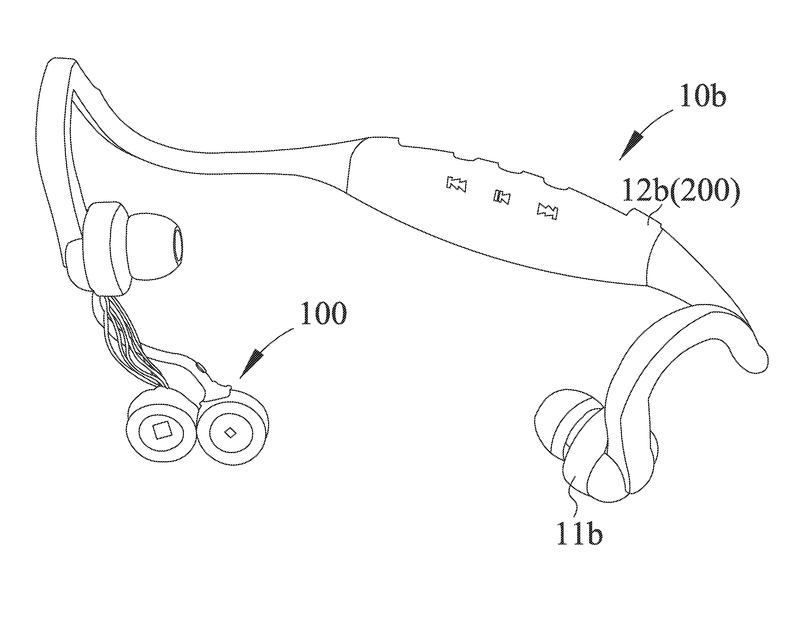
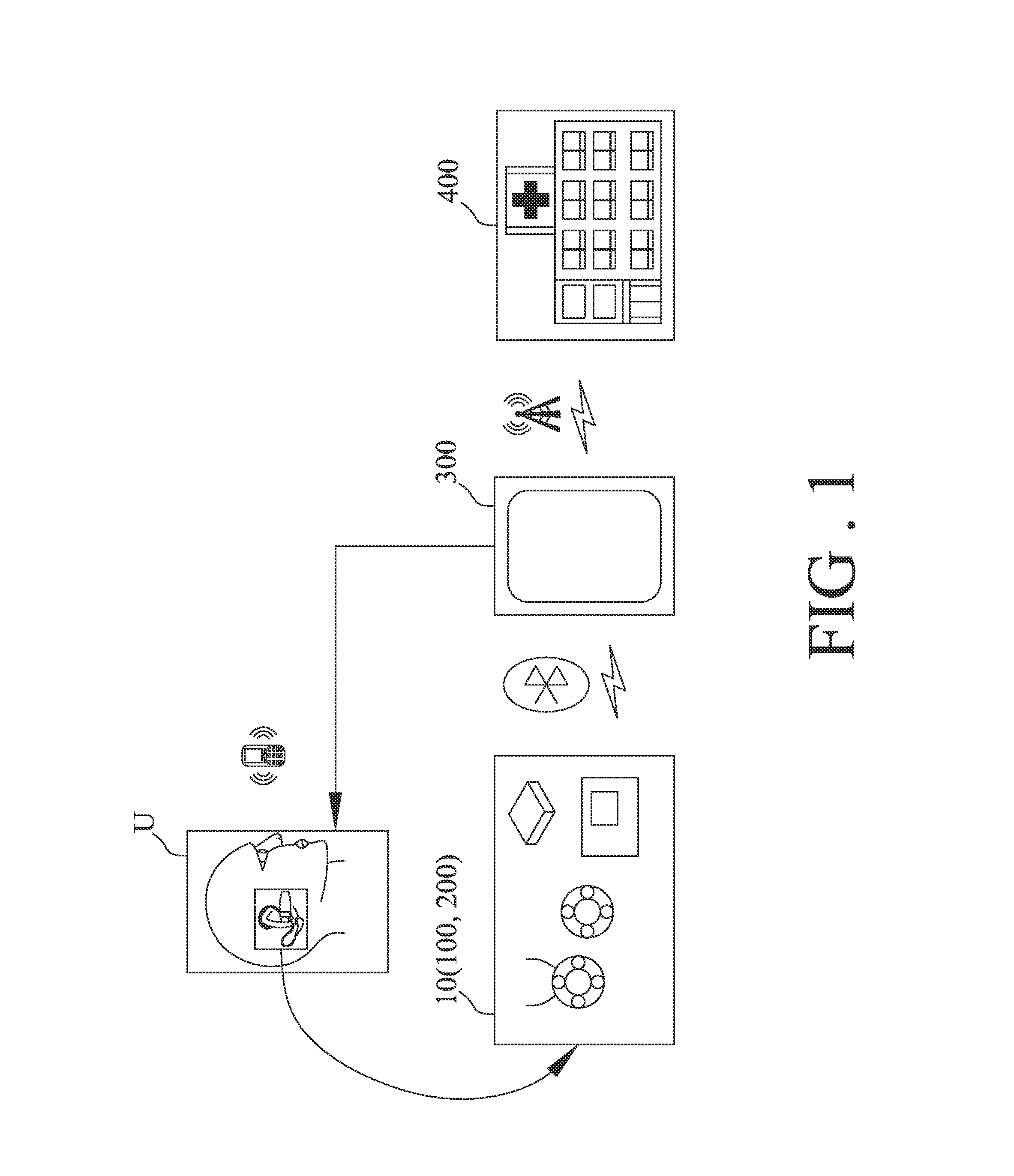
The invention provides a system for measuring and feedback on physiological signals in real-time. The system has a sensor module that can be worn by the user, with magnetic units to securely attach it to the body. This module reduces noise interference when sensing the motion of the user. Compared to previous designs, the sensor module improves the quality of the original signal by using two magnetic units. It can easily attach to the user's earlobe without affecting daily activities.

Problems solved by technology

The typical fingertip clip sensor module can be further adapted into various shapes, but all of them have common easily drop off drawback.
Because the fingertip clip sensor module can only loosely clamp the finger of the examinee to assure a comfortably clip without any painful pinch feeling in operation mode, it is easily dropped off due to inadvertently pull and drag or sudden movement of the examinee.
Though the finger ring sensor module solves the easily drop off drawback of the fingertip clip sensor module, but it creates another drawback that no universal ring size can meet various finger dimensions of different examinees.
However, the foregoing suite of measuring devices and medical monitor for conditioning the perceived brightness fluctuation form the fingertip clip sensor module and finger ring sensor module is always bulky and complicated in association, which confines the application being limited in clinical usage and cumbersome unable for daily living usage outside of clinics.
For fingertip clip sensor module, it has easily dropping off drawback and cumbersome drawback in associated suite of measuring devices and medical monitor.
For fingertip ring sensor module, it has drawback in no universal ring size able to meet various finger dimensions of different examinees in addition of cumbersome drawback in associated suite of measuring devices and medical monitor.
For headphone sensor module, it has drawback in being vulnerably affected by the noise interference of motion artifact.

Method used


Image

  • Real-time physiological signal measurement and feedback system
  • Real-time physiological signal measurement and feedback system
  • Real-time physiological signal measurement and feedback system

Examples


Embodiment Construction

[0027]In the following detailed description of the preferred embodiments, reference is made to the accompanying drawings which form a part hereof, and in which is shown by way of illustration specific embodiments in which the invention may be practiced. In this regard, directional terminology, such as “top,”“bottom,”“front,”“back,” etc., is used with reference to the orientation of the Figure(s) being described. The components of the present invention can be positioned in a number of different orientations. As such the directional terminology is used for purposes of illustration and is in no way limiting. On the other hand, the drawings are only schematic and the sizes of components may be exaggerated for clarity. It is to be understood that other embodiments may be utilized and structural changes may be made without departing from the scope of the present invention. Also, it is to be understood that the phraseology and terminology used herein are for the purpose of description and ...


PUM


Abstract

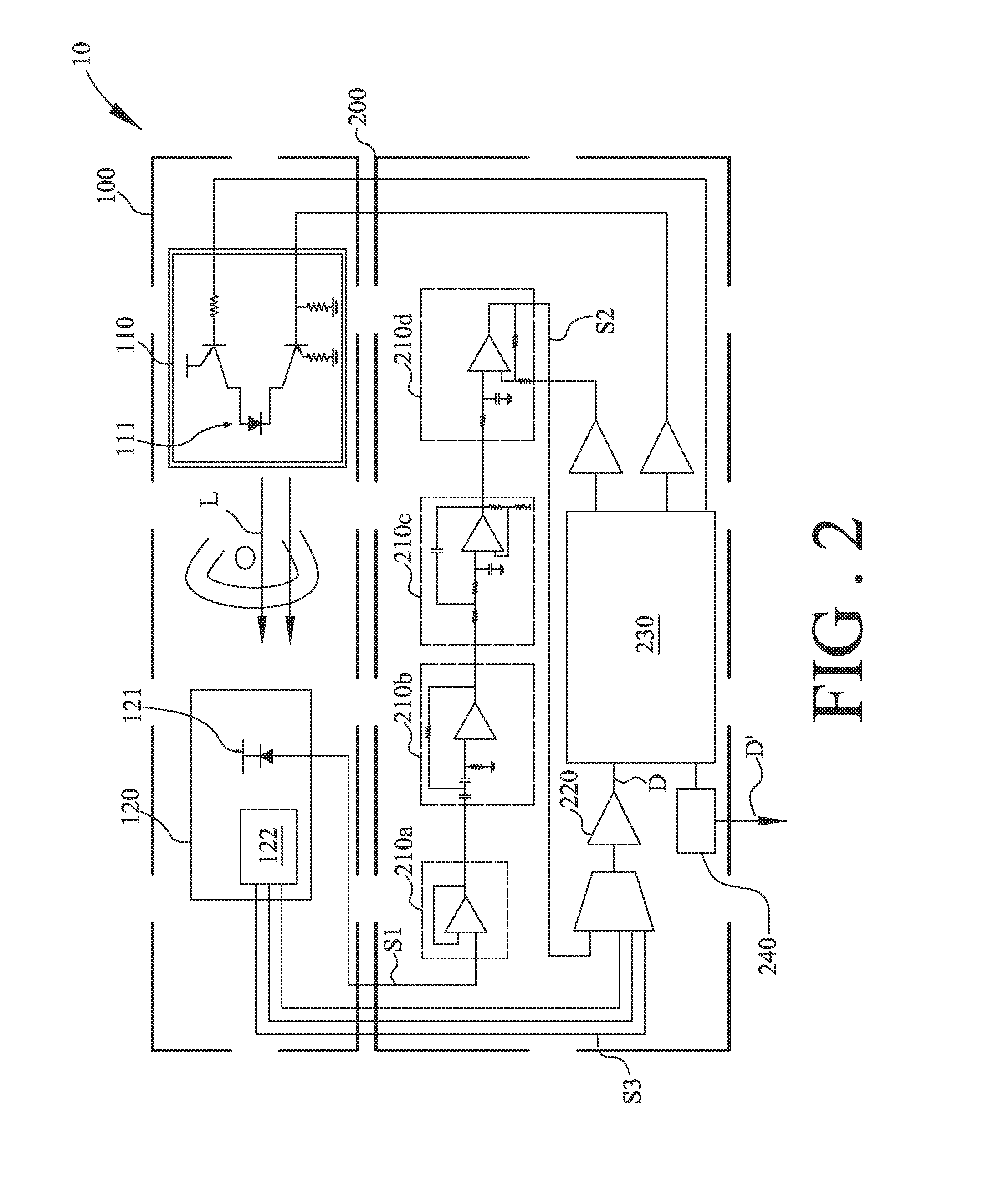
A real-time physiological signal measurement and feedback system is suitable to be worn on a body part of an user for decreasing the noise of motion, and includes a sensor module, a signal processing module and a feedback platform. The sensor module includes a first magnetic unit having a light emitting diode and a second magnetic unit having a photo-detector. The light emitting diode illuminates a light beam passing through the body part and being received by the photo-detector so as to generate an electric signal when both of the first and the second magnetic units attract mutually to sandwich the body part. The signal processing module converts the electrical signal into a digital signal. The feedback platform processes the digital signal to generate a physiological parameter, and is used as a multi-function driving recorder. An alarm is triggered or not by the feedback platform according to the physiological parameter.

Description

BACKGROUND OF THE INVENTION[0001](1) Field of the Invention[0002]The invention relates to an physiological signal measurement system, and especially relates to a signal measurement and feedback system for real-time photoplethysmograph.[0003](2) Description of the Prior Art[0004]Generally speaking, for the purpose of measuring physiological signal such as photoplethysmograph, two conventional sensing methods are popularly adopted: fingertip clip sensor module and finger ring sensor module. A typical fingertip clip sensor module mainly comprises a pair of shanks, which are crisscross pivotal jointed in respective middle section in scissors-like manner such that each shank serves as a prong of an integrated fingertip clip sensor module. Each shank includes a front jaw and a rear levering stem in addition to the middle pivotal section, which acts as a fulcrum at the pivotal joint. One front jaw of a shank contains a light-emitting diode (LED) while the other front jaw of another shank c...

Claims


Application Information

Patent Timeline
IPC IPC(8): A61B6/00A61B5/0245A61B5/11
CPCA61B5/11A61B5/6893A61B5/002A61B5/0059A61B5/02433G06F19/34A61B5/1113A61B5/1116A61B5/6816A61B5/683A61B2562/14A61B5/1112G16H40/67
Inventor LIN, YUAN-HSIANGLIN, CHIH-FONGYOU, HE-ZHONG
Owner NAT TAIWAN UNIV OF SCI & TECH
Learn More