
Dead-time compensation algorithm for 3-phase inverter using svpwm

a deadtime compensation and inverter technology, applied in the direction of dc-ac conversion without reversal, power conversion systems, electrical equipment, etc., can solve problems such as degraded control performance, and achieve the effect of minimizing the distortion of output voltag

Inactive Publication Date: 2013-04-11
KYUNGPOOK NAT UNIV IND ACADEMIC COOP FOUND +1
View PDF6 Cites 52 Cited by
  • Summary
  • Abstract
  • Description
  • Claims
  • Application Information

AI Technical Summary

Benefits of technology

The invention is a simple algorithm that reduces distortion and voltage loss in a 3-phase inverter using an SVPWM scheme. It takes into account the polarity of the load current and minimizes the impact of dead-time. The technical effect of the invention is to improve the performance of the inverter and minimize its output voltage issues.

Problems solved by technology

However, the difference between time to apply effective voltage, which is issued from the controller, and time to actually apply the effective voltage to a load is made due to dead-time applied in order to prevent an arm-short between power semiconductor switches.
In particular, such an influence is increased in the system requiring low voltage, so that the control performance may be degraded.

Method used


Image

  • Dead-time compensation algorithm for 3-phase inverter using svpwm
  • Dead-time compensation algorithm for 3-phase inverter using svpwm
  • Dead-time compensation algorithm for 3-phase inverter using svpwm

Examples


Embodiment Construction

[0033]The above object, other objects, and new features of the present invention will be more apparently comprehended with reference to the following description when taken in conjunction with the accompanying drawings.

[0034]Hereinafter, the structure according to the present invention will be described with reference to accompanying drawings.

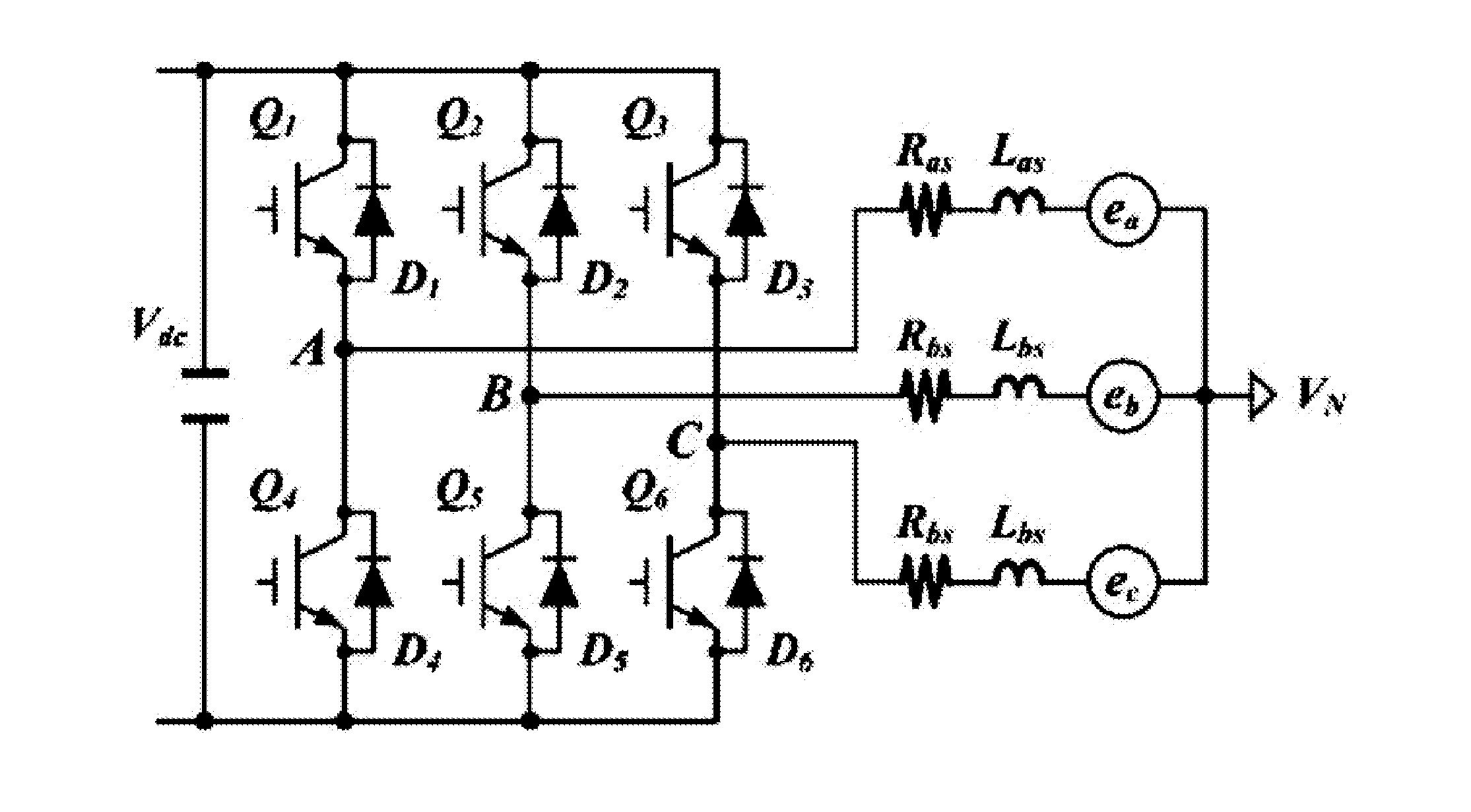
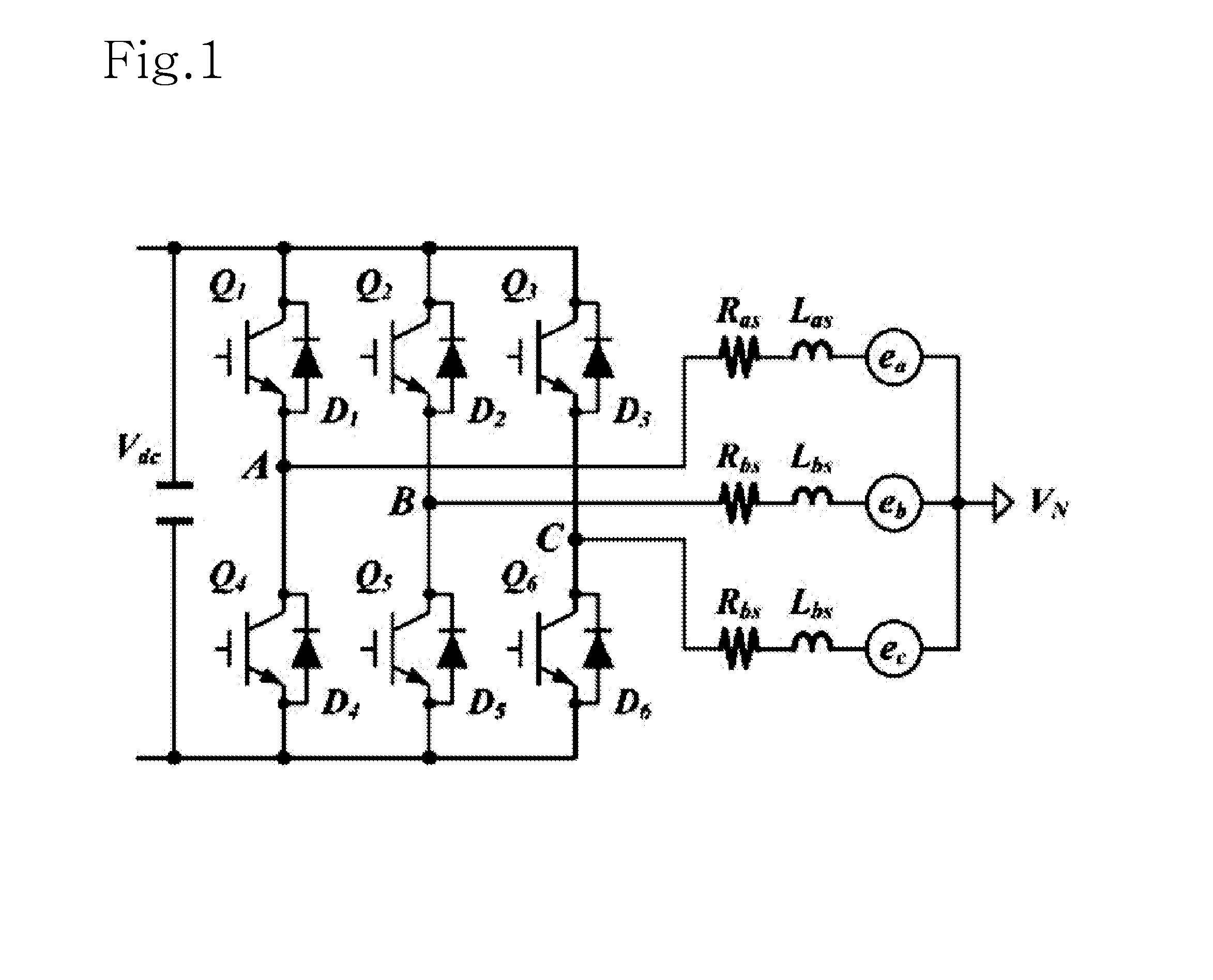
[0035]FIG. 1 is a circuit diagram showing the structure of a typical 3-phase inverter.

[0036]As shown in FIG. 1, in the 3-phase inverter, phases include power semiconductor switch transistors Q1 to Q6 of upper and lower arms (hereinafter, upper and lower power semiconductor switch transistors). In addition, phases A, B, and C are represented by using the power semiconductor switch transistors Q1 and Q4, the power semiconductor switch transistors Q2 and Q5, and the power semiconductor switch transistors Q3 and Q6, respectively, in which each pair of switch transistors have a series-connection.

[0037]In addition, the power semiconductor switch tran...


PUM


Abstract

Disclosed is a dead-time compensation method of a 3-phase inverter using an SVPWM scheme. The dead-time compensation method includes generating a switching signal having dead-time with respect to the power semiconductor switches of the upper and lower arms in order to obtain a predetermined output through the SVPWM scheme, detecting medium phase current from each phase current output through the switching signal, determining polarity of the medium phase current, and generating a switching signal by calculating switching time in order to compensate for time to apply effective voltage according to the polarity of the medium phase current. Through the dead-time compensation method, the distortion of the output voltage and the reduction of voltage having a fundamental wave in the output voltage, which are caused by the dead-time, are minimized through the switching of compensating for the time to apply effective voltage based on the polarity of the load current.

Description

BACKGROUND OF THE INVENTION[0001]1. Field of the Invention[0002]The present invention relates to a simple dead-time compensation algorithm for a 3-phase inverter using an SVPWM (Space Vector Pulse Width Modulation) scheme. In more particular, the present invention relates to a simple dead-time compensation algorithm for a 3-phase inverter using an SVPWM scheme, capable of minimizing the distortion of output voltage and the discontinuity of current when the polarity of phase current is switched, by compensating for dead-time applied in order to prevent arm-short between semiconductor switches of upper and lower arms when an electric motor is controlled by using a 3-phase SUPWM inverter based on semiconductor switches.[0003]2. Description of the Related Art[0004]Recently, as characteristics of power semiconductor switches are improved, and the switching technology thereof has been gradually developed, the performance of a power transformer is improved. Accordingly, the use of a voltag...

Claims


Application Information

Patent Timeline
IPC IPC(8): H02M7/537
CPCH02M7/53875H02M2007/53876H02M2001/385H02M1/385H02M7/53876H02M1/12H02M7/48
Inventor LEE, DONG HEEKIM, HONG MIN
Owner KYUNGPOOK NAT UNIV IND ACADEMIC COOP FOUND
Learn More