Supercharge Your Innovation With Domain-Expert AI Agents!

Transaxle

a technology of transaxle and rotor, which is applied in the direction of transmission, control device, vehicle components, etc., can solve the problems of increasing parts and costs, and achieve the effects of reducing the cost of the transaxle, enhancing the variation of the adaptable reduction mechanism, and reducing the cost of the reduction mechanism

Inactive Publication Date: 2013-04-11
KANZAKI KOKYUKOKI MFG
View PDF7 Cites 0 Cited by
  • Summary
  • Abstract
  • Description
  • Claims
  • Application Information

AI Technical Summary

Benefits of technology

The invention is a transaxle that includes a transmission differential unit. The unit includes a frictional transmission mechanism and a differential mechanism. The frictional transmission mechanism includes an input shaft, a drive disc, and a driven disc. The differential mechanism includes a pair of coaxial output shafts and a differential casing. The driven disc is ring-shaped and fitted on the outer portion of the differential casing so as to be unrotatable relative to the differential casing and slidable in the axial direction of the output shafts. This design ensures the slidable range of the driven disc while the differential casing unrotatably connects to it, making the space between the output shafts compact and reducing the size, weight, parts, and costs of the transaxle. The transaxle also includes a pair of axles and a pair of reduction mechanisms interposed between the output shafts and the axles to achieve the required speed-reduction effect. The axles can be eccentric to the output shafts, enhancing the variation of the reduction mechanisms. The transaxle is housed in a single or separate housing, reducing the number of parts and cost. The drive disc has a region where it does not contact the disc surface, acting as a clutch to set the output shafts in a neutral state when their rotary direction is changed. This eliminates the need for an additional clutch and reduces shock when changing the output shafts' rotary direction.

Problems solved by technology

To drivingly connect the frictional transmission unit to the differential unit, the reduction gear train, including a counter shaft and counter gears, must be interposed between the frictional transmission unit and the differential unit, thereby increasing parts and costs.

Method used


Image

  • Transaxle
  • Transaxle
  • Transaxle

Examples


Embodiment Construction

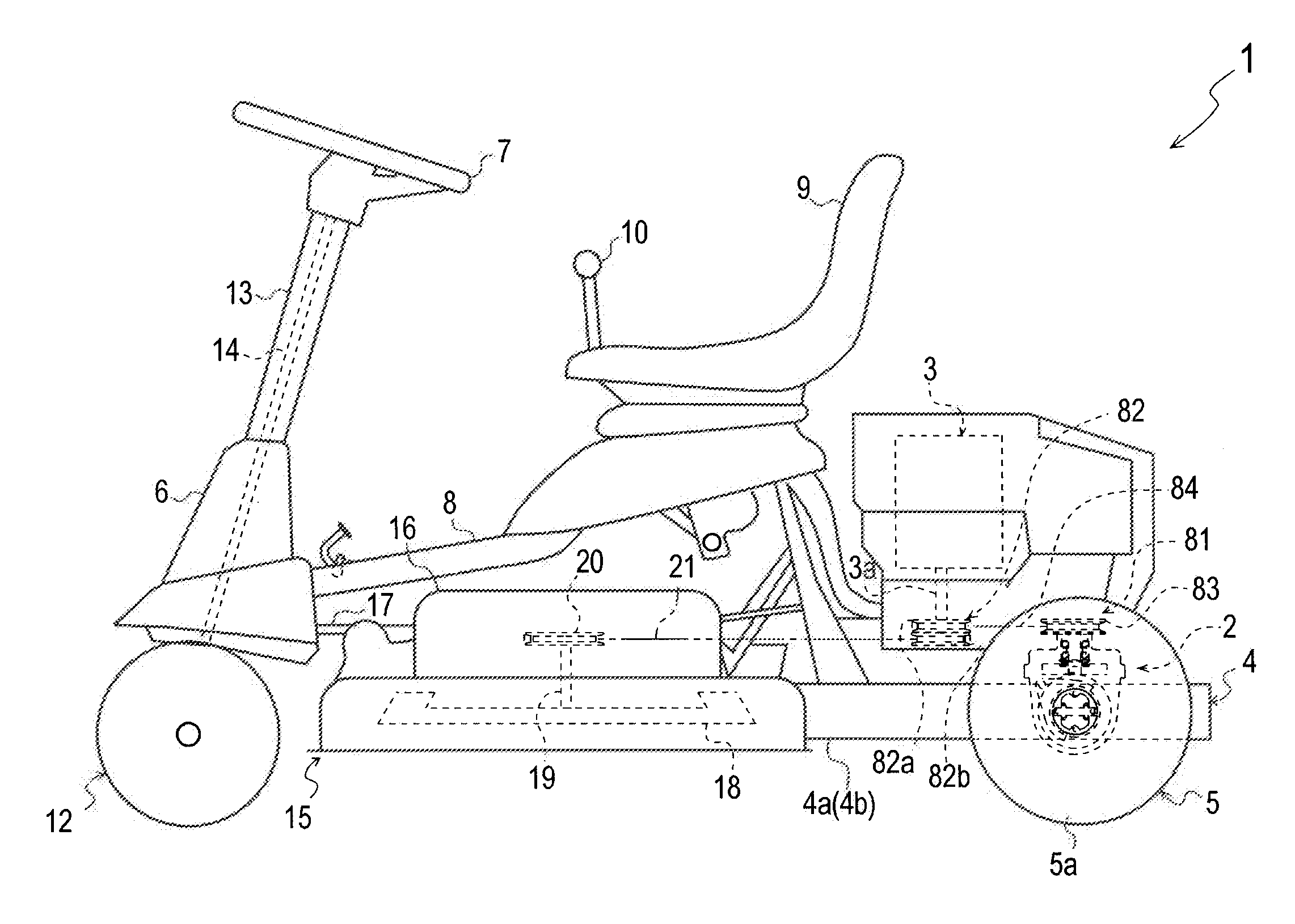
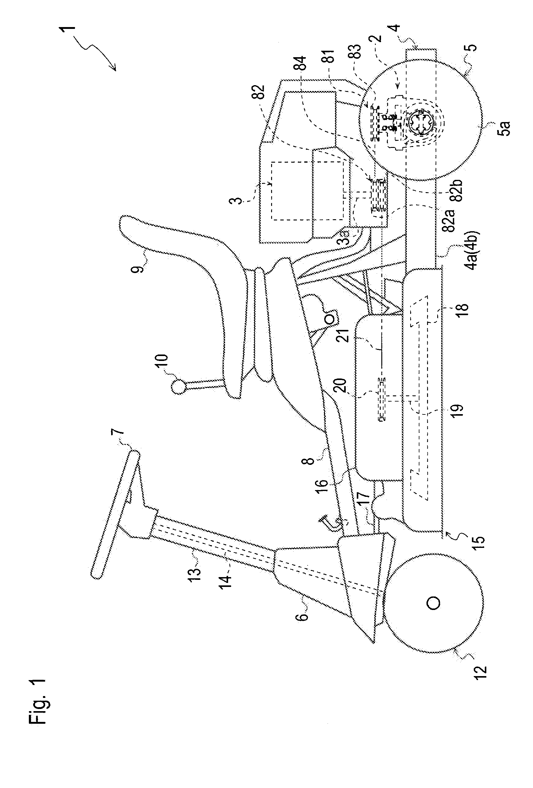
[0032]Referring to FIGS. 1 and 2, a lawn mower 1 will be described. Words “proximal” and “distal” are used in all embodiments of transaxles on an assumption that a “proximal” member or portion is closer to a lateral middle point of the transaxle than a “distal” member or portion.

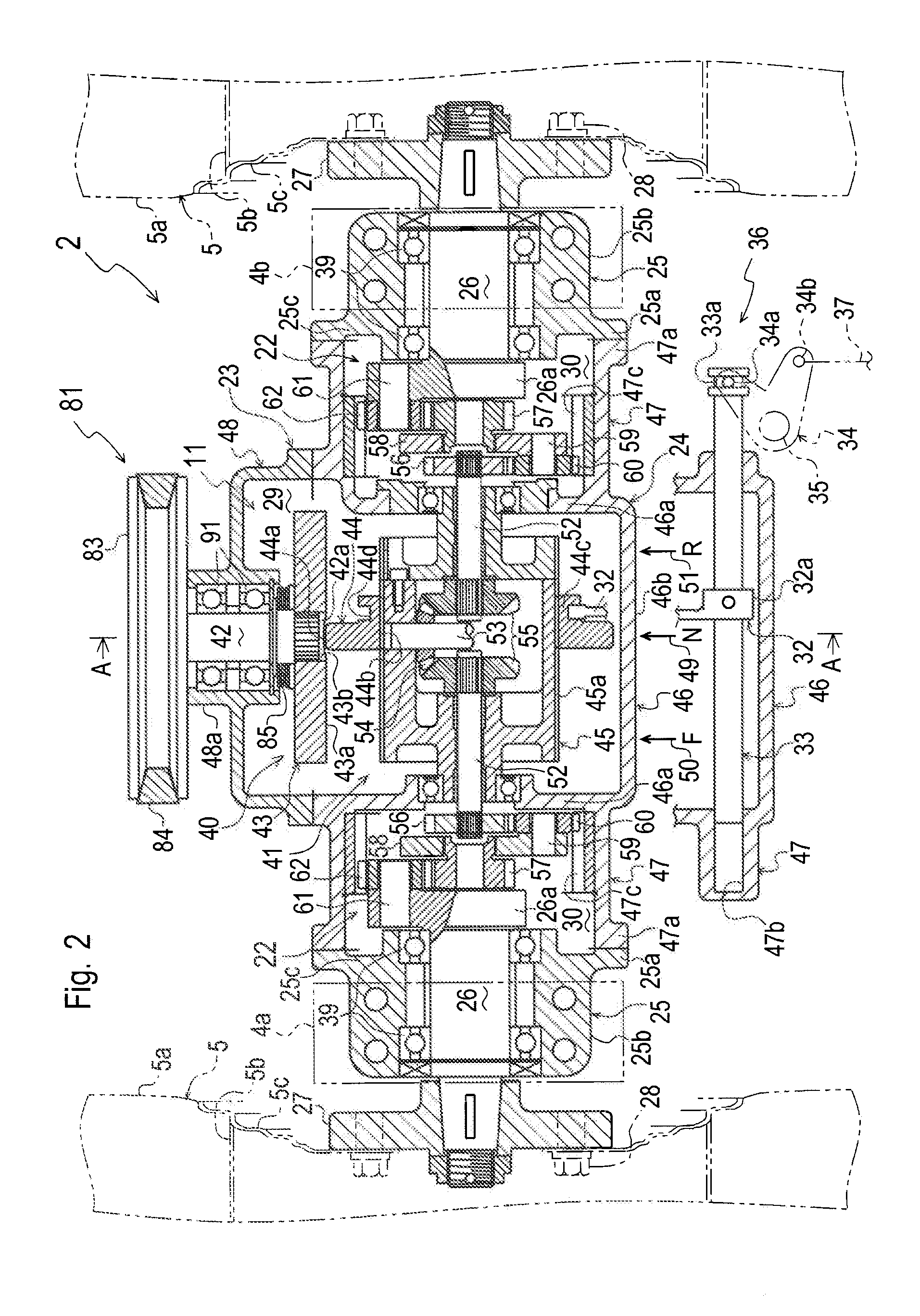
[0033]Lawn mower 1 includes a vehicle body frame 4 that is formed in a rectangular shape when viewed in plan so as to have right and left vertical side plates 4a and 4b. Right and left drive wheels serve as rear wheels 5 each of which is disposed laterally outward of a rear portion of each of right and left side plates 4a and 4b. A transaxle 2 is supported by right and left side plates 4a and 4b and is disposed between right and left rear wheels 5 so as to drive rear wheels 5.

[0034]A steering base 6 is mounted upward on a front end portion of vehicle body frame 4, and a steering column 13 is extended upward from steering base 6. A steering wheel 7 serving as a steering manipulator is disposed on a top of ste...


PUM


Abstract

A transaxle comprises a transmission differential unit including a frictional transmission mechanism and a differential mechanism. The frictional transmission mechanism includes an input shaft, a drive disc provided on the input shaft, and a driven disc whose outer peripheral edge frictionally contacts a disc surface of the drive disc. The differential mechanism includes a pair of coaxial output shafts, and a differential casing differentially connecting the output shafts to each other. The driven disc is ring-shaped and is fitted at an inner peripheral portion thereof on an outer peripheral portion of the differential casing so as to be unrotatable relative to the differential casing and so as to be slidable on the outer peripheral portion of the differential casing in the axial direction of the output shafts.

Description

BACKGROUND OF THE INVENTION[0001]1. Field of the Invention[0002]The present invention relates to a transaxle including a frictional transmission mechanism and a differential mechanism.[0003]2. Related Art[0004]As disclosed by JP 2004-36836 A (hereinafter, “Reference 1”), there is a well-known conventional frictional transmission unit. This frictional transmission unit includes an input shaft to be drivingly connected to a power source, a frictional drive disc fixed on the input shaft, an output shaft extended perpendicular to the input shaft, and a frictional driven disc fitted on the output shaft so as to be unrotatable relative to the output shaft and so as to be axially slidable along the output shaft. A peripheral edge of the driven disc frictionally contacts any portion of a disc surface of the drive disc. The driven disc is slid along the output shaft so as to change the contact position of the driven disc with the drive disc, i.e., the position of the driven disc relative to ...

Claims


Application Information

Patent Timeline
Patent Type & Authority Applications(United States)
IPC IPC(8): F16H37/08
CPCB60K17/16B60K17/046
Inventor ISHINO, FUMITOSHIMIYAKE, ETSUONISHIZAWA, TAKASHI
Owner KANZAKI KOKYUKOKI MFG
Features
  • R&D
  • Intellectual Property
  • Life Sciences
  • Materials
  • Tech Scout
  • Unparalleled Data Quality
  • Higher Quality Content
  • 60% Fewer Hallucinations
Learn More