Methods for evaluating inflow and outflow in a subterraean wellbore

a wellbore and subterranean technology, applied in the field of geotechnical field measurements, can solve the problems of prohibitively expensive and relatively minor interruptions in drilling operations, and no disclosure of methods for computing sequential

Active Publication Date: 2013-04-11
SCHLUMBERGER TECH CORP
View PDF7 Cites 76 Cited by
  • Summary
  • Abstract
  • Description
  • Claims
  • Application Information

AI Technical Summary

Benefits of technology

[0007]The disclosed embodiments may provide various technical advantages. For example, disclosed embodiments may provide for timely detection of an inflow event, which in turn provides for timely mitigation. In many drilling operations timely mitigation may be required to prevent a dangerous kick. Moreover, disclosed embodiments may enable a density of an inflow constituent to be computed, thereby possibly distinguishing between a gaseous, oil, or connate water based inflow event. Disclosed methods may further enable a lost circulation event to be identified. In certain embodiments a measured depth interval of the inflow or outflow event may also be located.

Problems solved by technology

There is considerable interest in the industry in risk avoidance since even relatively minor interruptions in drilling operations can be prohibitively expensive.
While along string pressure and temperature measurements are known in the art, there has been no disclosure of methods for computing sequential and non-sequential pressure and temperature interval densities nor any methods of utilizing such interval densities to characterize the subterranean formations, the drilling fluid, or the drilling process.

Method used


Image

  • Methods for evaluating inflow and outflow in a subterraean wellbore
  • Methods for evaluating inflow and outflow in a subterraean wellbore
  • Methods for evaluating inflow and outflow in a subterraean wellbore

Examples


Embodiment Construction

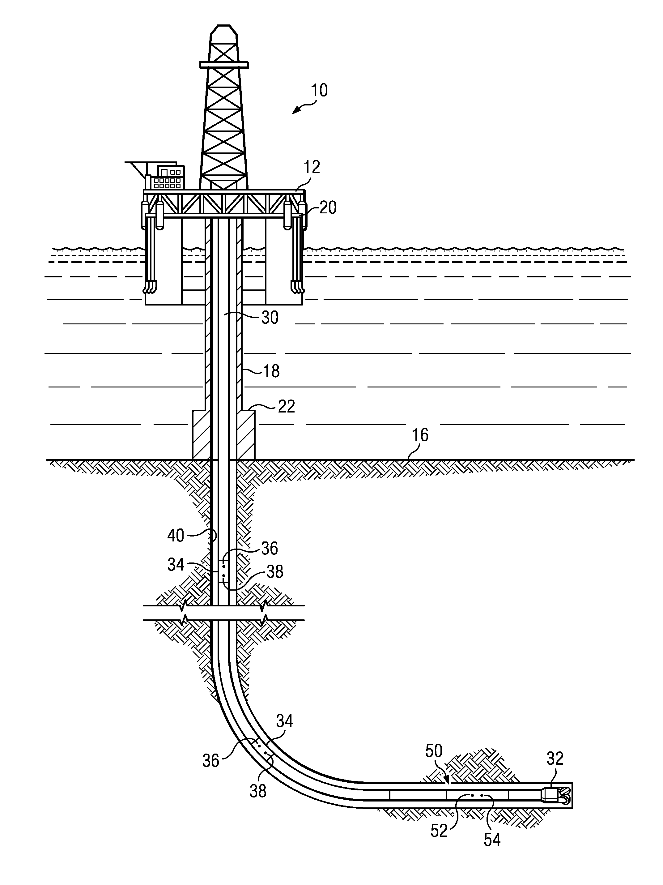
[0039]FIG. 1 depicts a drilling rig 10 suitable for using various method embodiments disclosed herein. A semisubmersible drilling platform 12 is positioned over an oil or gas formation (not shown) disposed below the sea floor 16. A subsea conduit 18 extends from deck 20 of platform 12 to a wellhead installation 22. The platform may include a derrick and a hoisting apparatus for raising and lowering a drill string 30, which, as shown, extends into borehole 40 and includes a drill bit 32 deployed at the lower end of bottom hole assembly (BHA) 50. In the depicted embodiment, drill string 30 includes a plurality of joints of wired drill pipe and therefore provides a high bandwidth digital communications channel (e.g., a bandwidth on the order of 5 kilobits / sec) between the BHA 50 and the surface.

[0040]Drill string 30 includes a plurality of longitudinally spaced wired drill pipe repeater subs 34, at least some of which include annular pressure and temperature sensors 36 and 38. These se...


PUM


Abstract

A method for evaluating inflow or outflow in a subterranean wellbore includes acquiring first and second axially spaced pressure measurements in the wellbore. The pressure measurements may then be processed to obtain an interval density of drilling fluid between the measurement locations. A tool string including a large number of axially spaced pressure sensors (e.g., four or more or even six or more) electronically coupled with a surface processor via wired drill pipe may be used to obtain a plurality of interval densities corresponding to various wellbore intervals. The interval density may be measured during static conditions or while drilling and may be further processed to compute a density of an inflow constituent in the annulus. Changes in the computed interval density with time may be used as an indicator of either an inflow event or an outflow event.

Description

CROSS REFERENCE TO RELATED APPLICATIONS[0001]This application claims the benefit of U.S. Provisional Application Ser. No. 61 / 527,948 entitled Interpretation Methodologies and Calculations for Wired Drill Pipe Along String Measurements of Pressure and Temperature, filed Aug. 26, 2011.FIELD OF THE INVENTION[0002]Disclosed embodiments relate generally to geotechnical field measurements and more particularly to Along String Measurements (ASM) that may be incorporated in repeater hardware sections of Wired Drill Pipe (WDP). Methods are disclosed for computing sequential and non-sequential pressure and temperature measurements in these repeaters as well as pressures and temperatures measured by Bottom Hole Assembly (BHA) components. Methods are further disclosed for utilizing these measurements to characterize the subterranean formations, the drilling fluid, and the drilling process.BACKGROUND INFORMATION[0003]During drilling operations, measurements of downhole conditions taken while dri...

Claims


Application Information

Patent Timeline
Patent Type & Authority Applications(United States)
IPC IPC(8): E21B47/06
CPCE21B47/06E21B47/04E21B49/003E21B47/003G01V3/38E21B47/10E21B49/0875E21B21/08E21B34/06E21B43/12
Inventor RASMUS, JOHNLESSO, WILLIAMJAMES, JOHN
Owner SCHLUMBERGER TECH CORP
Why Eureka
Try Eureka