Intelligent Control Wave Energy Power Generating System

a technology of intelligent control and power generation system, applied in mechanical equipment, machines/engines, gearing, etc., can solve the problems of inability to use in real wave conditions, too fragile to achieve real wave conditions, and unpredictable wave directions, etc., to achieve the effect of improving energy conversion efficiency, reducing the energy lost in raising the buoy, and increasing the wave energy

Active Publication Date: 2013-04-18
LEE MICHAEL FUQUAN
View PDF8 Cites 16 Cited by
  • Summary
  • Abstract
  • Description
  • Claims
  • Application Information

AI Technical Summary

Benefits of technology

[0008]Because of the irregularity of wave directions, the waves may push the buoy in any horizontal direction, impacting the power input shaft coupled therewith. The motion translating assembly also includes a flexible pivot device connecting the power input shaft and the gear transmission assembly. The flexible pivot device absorbs any impact caused by wave-motion irregularity. This prevents the power input shaft from breaking and the gears in the gear transmission assembly from disengaging.
[0009]The counterbalancing and maintenance device is coupled with the buoy via a cable to improve the energy conversion efficiency and provide system protection under severe wave and weather conditions. It...

Problems solved by technology

However, these apparatuses usually have three limitations.
First, they are too fragile to use in real wave conditions.
Wave directions are usually unpredictable.
Variations of wave direction will cause unpredictable motion of the gearing assembly, which will result in extra wear and even breakage of the gearing assembly.
Second, these apparatuses are inefficient in converting wave energy into electric energy.
A substantial energy loss occurs each time the entire floating assembly is uplifted by wave action, leaving less energy for driving the geari...

Method used


Image

  • Intelligent Control Wave Energy Power Generating System
  • Intelligent Control Wave Energy Power Generating System
  • Intelligent Control Wave Energy Power Generating System

Examples


Embodiment Construction

One Embodiment—FIGS. 1-9

[0087]While the present invention is disclosed with reference to the embodiments described herein, it should be clear that the present invention should not be limited to such embodiment. Therefore, the description of the embodiments herein is only illustrative of the present invention and should not limit the scope of the invention as claimed.

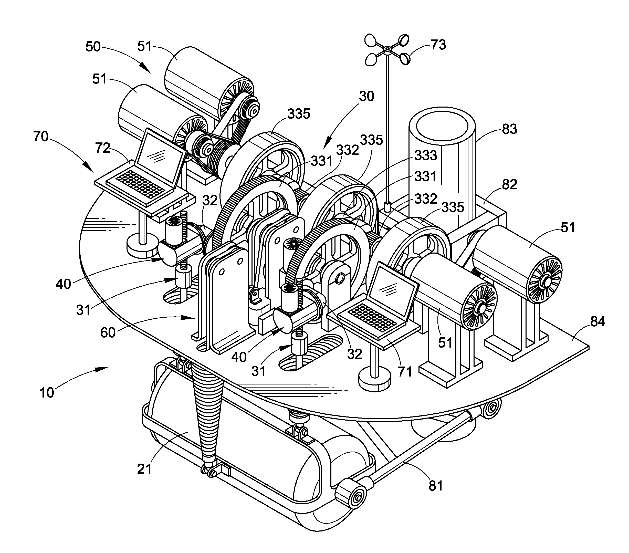
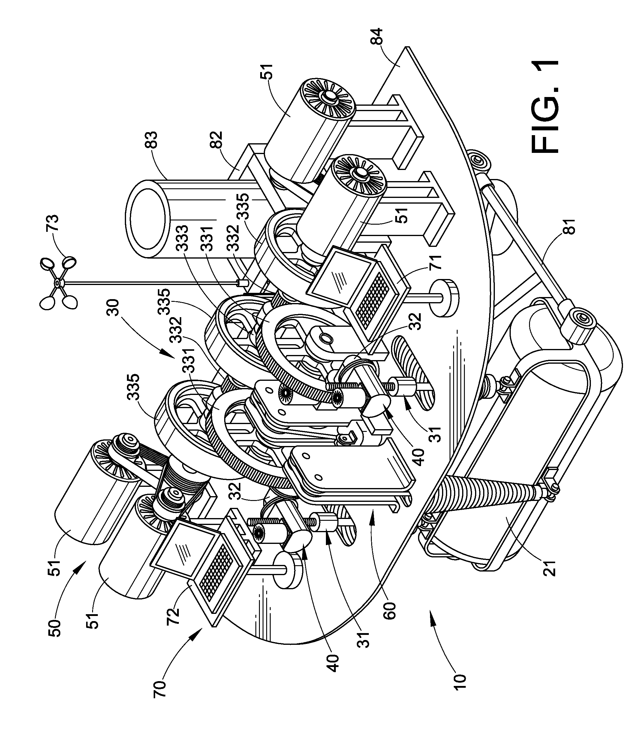
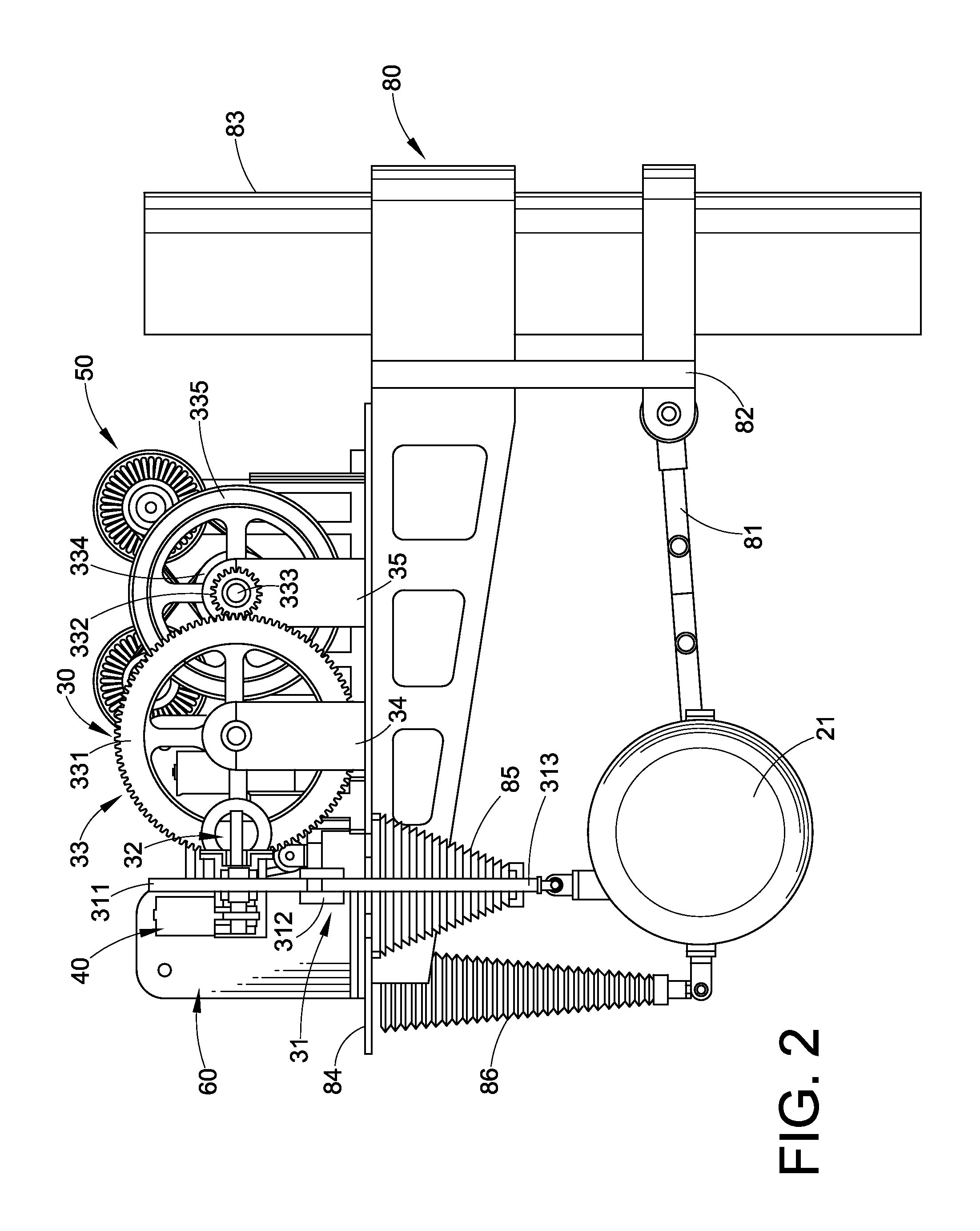
[0088]The present invention provides an intelligent control wave energy power generating system 10 which generates electric energy from waves. One embodiment of the intelligent control wave energy power generating system 10 comprises a buoy or float 21, a motion translating assembly 30, a threaded rod adjustment device 40, a generator assembly 50, a counterbalancing and maintenance device 60, an intelligent control system 70, a platform assembly 80, and an openable cover 90.

[0089]FIG. 1 shows the intelligent control wave energy power generating system 10 without the openable cover 90. The buoy or float 21 floats on water...


PUM


Abstract

A system and method for converting wave energy into electric energy in an intelligent, practical, and efficient manner. The system utilizes a power input shaft coupled with a vertically reciprocating buoy to rotate a crank gear and a ratchet gear meshing therewith. When the gears rotate, a plurality of generators coupled therewith produce electric energy. A flexible pivot device connects the power input shaft and the crank gear for absorbing impacts against the system from irregular and variable passing waves. The power input shaft is adjusted in response to water level fluctuations for maximum efficiency. A counterbalancing and maintenance device is coupled with the buoy to improve energy conversion efficiency and to uplift the buoy to a safe position in extreme conditions. An intelligent control system is included to monitor, control, and optimize the operations of the system.

Description

CROSS-REFERENCE TO RELATED APPLICATIONS[0001]The present invention claims priority from U.S. Provisional Patent Application No. 61 / 397,257 to Michael Fuquan Lee, filed on Jun. 9, 2010, and titled Wave Energy Power Plant, which is hereby incorporated in its entirety by reference.BACKGROUNDPrior Art[0002]Waves in oceans and lakes have great potential as an alternative energy source. Wave energy is clean, renewable, and vastly available. The estimated amount of wave energy available in U.S. alone is 2,100 terawatt-hours (TWh) per year, about one fourth of annual U.S. energy imports. To make wave energy useful, wave energy is transformed into other energy forms, usually electric energy.[0003]Prior inventions for generating power from waves have provided apparatuses that often include a floating device, a gearing assembly, and an electric generating assembly. The floating device is connected to the gearing assembly such that when waves push the floating device the vertical motion of wave...

Claims


Application Information

Patent Timeline
IPC IPC(8): F03B13/18F16H37/12
CPCF03B13/186F05B2260/4031Y10T74/18208F16H37/124Y02E10/38F03B13/1815Y02E10/30
Inventor LEE, MICHAEL FUQUAN
Owner LEE MICHAEL FUQUAN
Why Eureka
Try Eureka