Flow rate control device, diagnostic device for use in flow rate measuring mechanism or for use in flow rate control device including the flow rate measuring mechanism and recording medium having diagnostic program recorded thereon for use in the same

a flow rate control and flow rate technology, applied in fluid pressure control, process and machine control, instruments, etc., can solve the problems of inability to manufacture a semiconductor having a desired performance, inability to accurately measure the flow rate in some cases, and likely caused errors, so as to suppress the increase of manufacturing costs and reduce the number of parts

Inactive Publication Date: 2013-04-18
HORIBA STEC CO LTD
View PDF0 Cites 25 Cited by
  • Summary
  • Abstract
  • Description
  • Claims
  • Application Information

AI Technical Summary

Benefits of technology

[0024]Thus, according to the flow rate control device, in a diagnostic device for use in the flow rate measuring mechanism, or for use in the flow rate control device which includes the flow rate measuring mechanism and recording medium having a diagnostic program recorded thereon for use in the same of the present invention, as a configuration for diagnosing an abnormality, it is sufficient to provide only one sensor other than the flow rate measuring mechanism for outputting the measurement flow rate value to be used in the feedback control. Hence, the number of parts can be reduced so as to suppress the increase of the manufacturing cost. In addition, since the diagnosis of an abnormality of the measurement flow rate value is performed based on a variation amount of the measurement pressure value when fluid is in a stable state, it becomes possible to diagnose an abnormality of the measurement flow rate value with an accuracy equal to or higher than that in a conventional configuration, even in the case where the number of the diagnostic sensors is smaller than that in the conventional configuration.

Problems solved by technology

Furthermore, some of the products of the process gas can easily adhere to an inside of a fine sensor flow channel for measuring a flow rate, such as a laminar element for diverting the fluid, and if the products adhere, clogging may occur so that an accurate flow rate cannot be measured in some cases.
If a flow rate measurement value measured by the flow rate measuring mechanism is inaccurate, an error may be likely caused in an actual flow rate of the process gas flowing into the chamber even if the flow rate control valve is accurately controlled.
Accordingly, it becomes impossible to manufacture a semiconductor having a desired performance.
In this configuration, if products of the process gas adhere and the like so that the orifice is clogged or an effective sectional area thereof is changed, it becomes impossible to introduce a process gas at a desired flow rate value.
However, a demand for reducing costs is severe in the field of semiconductor manufacturing.
On the other hand, if the number of the sensors is simply reduced, it becomes difficult using the above configuration, to precisely diagnose, based on a quantitative evaluation, whether or not the measurement flow rate value used in the feedback control indicates a correct value to an acceptable degree, or to accurately diagnose whether or not clogging actually occurs in the flow channel.

Method used


Image

  • Flow rate control device, diagnostic device for use in flow rate measuring mechanism or for use in flow rate control device including the flow rate measuring mechanism and recording medium having diagnostic program recorded thereon for use in the same
  • Flow rate control device, diagnostic device for use in flow rate measuring mechanism or for use in flow rate control device including the flow rate measuring mechanism and recording medium having diagnostic program recorded thereon for use in the same
  • Flow rate control device, diagnostic device for use in flow rate measuring mechanism or for use in flow rate control device including the flow rate measuring mechanism and recording medium having diagnostic program recorded thereon for use in the same

Examples


first embodiment

[0045]The following describes a flow rate control device and a diagnostic device 200 according to the present invention, referring to the accompanying drawings.

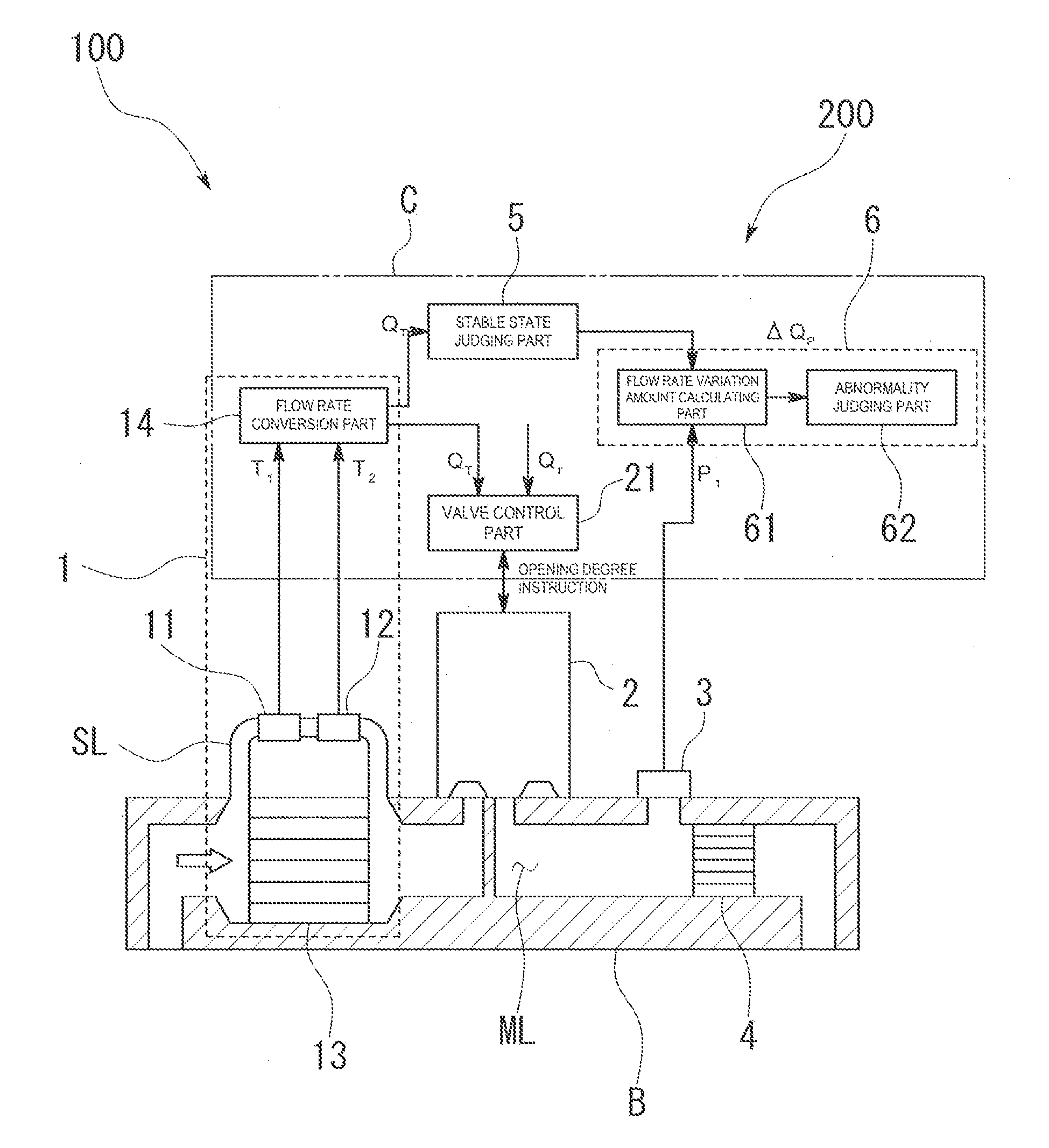
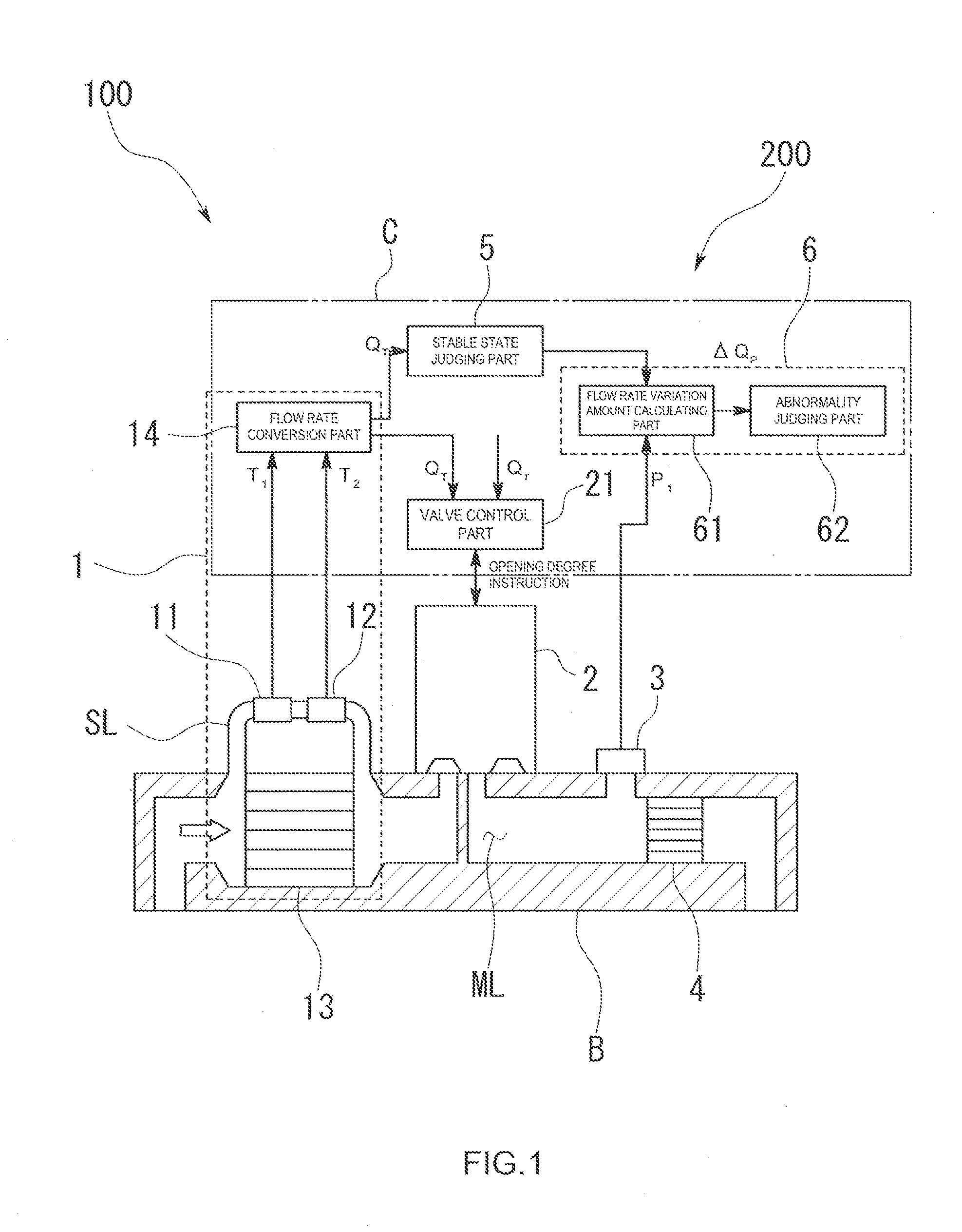
[0046]The flow rate control device of the first embodiment is configured by a mass flow controller 100 which is used for supplying a process gas containing raw materials required for deposition in a chamber such as a chemical vapor deposition (CVD) device, for example, in semiconductor manufacture. As shown in a schematic view of FIG. 1, the mass flow controller 100 is configured to have a flow channel ML which is formed by forming a through path inside a block body B of a substantially rectangular parallelepiped shape, wherein equipment for controlling fluid and various kinds of equipment for constituting the diagnostic device 200 are attached to an upper surface of the block body B so that the mass flow controller 100 is packaged.

[0047]More specifically, the mass flow controller 100 includes a flow rate measuring mechanism,...

second embodiment

[0074]That is, in the mass flow controller 100 and diagnostic device 200 of the second embodiment, the abnormality diagnosing part 6 includes a pressure variation amount calculating part 63 for calculating a variation amount of the measurement pressure value and an abnormality judging part 62 configured to judge the measurement flow rate value to be abnormal in the case where an absolute value of the variation amount of the pressure calculated by the pressure variation amount calculating part 63 is equal to or larger than a predetermined value.

[0075]The pressure variation amount calculating part 63 is configured to sequentially calculate a variation amount as to the measurement pressure value P1 measured by the pressure sensor 3 when the fluid is in a stable state. In the second embodiment, the pressure variation amount calculating part 63 is configured to calculate a difference as a variation amount as in the first embodiment. More specifically, the pressure variation amount calcul...


PUM


Abstract

The flow rate control device is provided with: a fluid resistor provided on the flow channel; a pressure sensor provided in any one of an upstream side or a downstream side of the fluid resistor; a stable state judging part configured to judge, based on the measurement flow rate value or a measurement pressure value measured by the pressure sensor, whether or not a state of the fluid flowing through the flow channel is in a stable state; and an abnormality diagnosing part configured to diagnose an abnormality of the measurement flow rate value based on a variation amount of the measurement pressure value in the case where the stable state judging part judges that the state of the fluid is in a stable state.

Description

TECHNICAL FIELD[0001]The present invention relates to a flow rate control device and the like having a configuration for diagnosing an abnormality of a measurement flow rate value indicated by a flow rate measuring mechanism for measuring a flow rate of fluid flowing through a flow channel.BACKGROUND ART[0002]For example, in manufacturing semiconductor products and the like, it is necessary that a process gas containing raw materials required for deposition is accurately supplied at a target flow rate with high accuracy while a wafer is placed in a chamber of, for example, a chemical vapor deposition (CVD) device.[0003]For controlling a flow rate of, for example, a process gas, a mass flow controller is provided on a flow channel connected to the chamber. A flow channel is formed in this mass flow controller, and the mass flow controller is configured as one package composed of a block body provided with various kinds of flow rate control equipment attached thereto, a flow rate meas...

Claims


Application Information

Patent Timeline
Patent Type & Authority Applications(United States)
IPC IPC(8): G05D7/06G01F1/34
CPCG01F1/696G05D7/0635G01F5/00G01F1/6965Y10T137/776Y10T137/7761G01F1/00G05D7/06G05D16/02H01L21/02
Inventor YASUDA, TADAHIROHAYASHI, SHIGEYUKITAKAHASHI, AKITOSHIMIZU, TETSUO
Owner HORIBA STEC CO LTD
Why Eureka
Try Eureka