Light Integrator for Rectangular Beam Cross Sections of Different Dimensions

a technology of integrators and cross sections, applied in the field of light integrators, can solve the problems of disadvantages of light integrators, complex manufacture, and disadvantages in terms of their manufacture, and achieve the effect of simple manufacturing

Inactive Publication Date: 2013-04-18
JENOPTIK OPTICAL SYST
View PDF3 Cites 2 Cited by
  • Summary
  • Abstract
  • Description
  • Claims
  • Application Information

AI Technical Summary

Benefits of technology

[0014]The invention is based on the object of providing a stable hollow integrator that is simple to manu

Problems solved by technology

The applicant of US 2005/0213333 A1 is of the opinion that such a light integrator is disadvantageous owing to the configuration and arrangement of the glass plates with respect to one another and their exclusively integrally bonded connection.
Such a hollow integrator certainly has a higher stability, but its

Method used


Image

  • Light Integrator for Rectangular Beam Cross Sections of Different Dimensions
  • Light Integrator for Rectangular Beam Cross Sections of Different Dimensions
  • Light Integrator for Rectangular Beam Cross Sections of Different Dimensions

Examples


Embodiment Construction

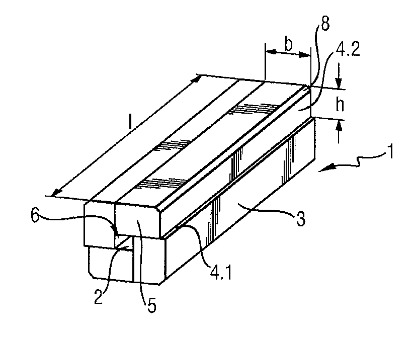
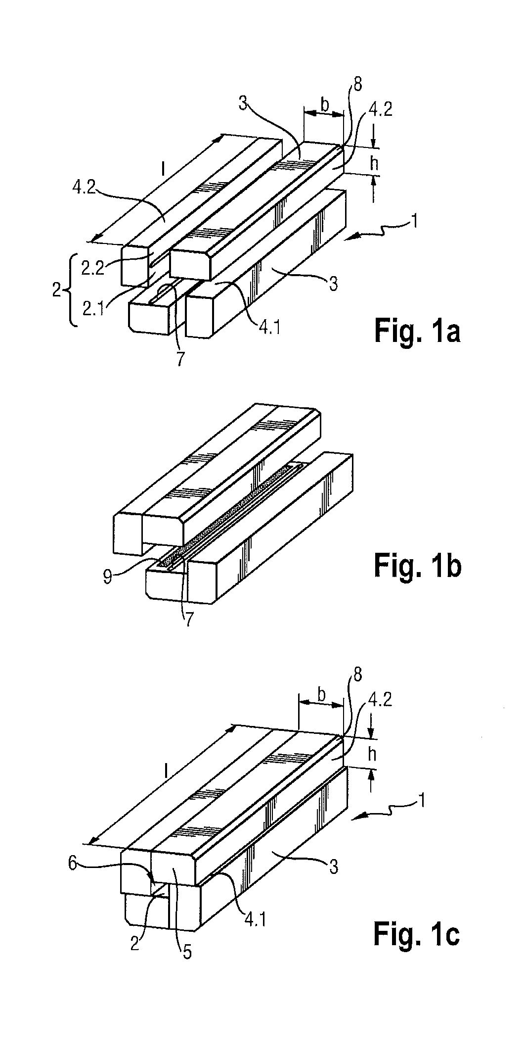
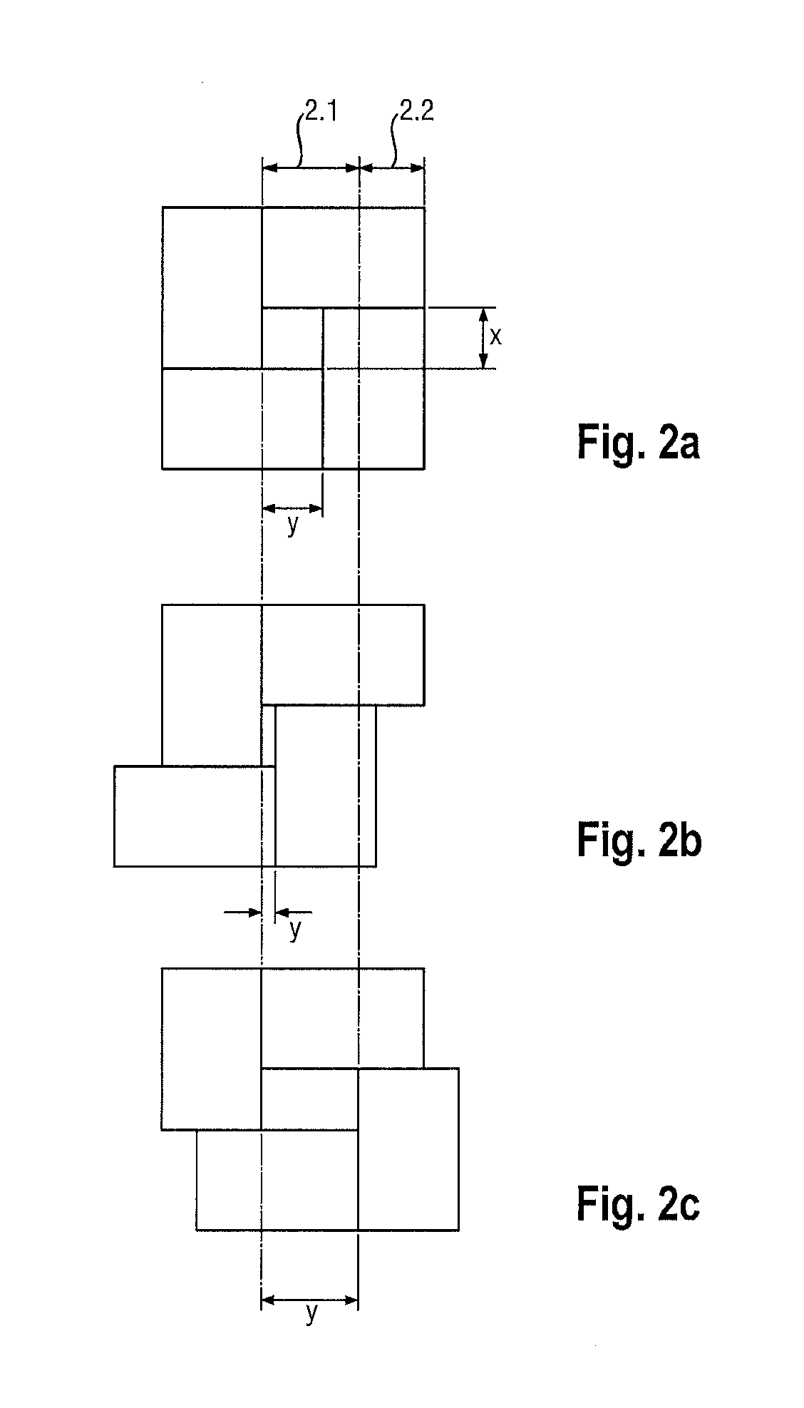
[0022]A light integrator according to the invention illustrated in FIGS. 1a to 1c comprises four identical, parallelepipedal glass plates 1. They have in each case an inner side 2 and an outer side 3, with a length l and a width b, and a first and a second longitudinal side 4.1, 4.2 and two end faces 5 with a height h. The inner sides 2 are subdivided into in each case a mirror-coated, optically active surface 2.1, and an adhesive surface 2.2, which includes a groove 7, which runs in a longitudinal direction and adjoins the optically active surface 2.1.

[0023]By producing all glass plates 1 as what is referred to as identical parts with a simple geometric shape, the manufacture complexity and thus the manufacturing costs can be kept low.

[0024]For the quality of the beam homogenization and the shaping of an exactly rectangular beam cross section of a light bundle that is guided through the light integrator, the quality of the optically active surface 2.1 and the perpendicularity betwe...


PUM


Abstract

A light integrator having four parallelepipedal glass plates which have an identical width. Each plate has an inner side and an outer side with a length, as well as a first and a second longitudinal side and two end faces with a height, the plates are arranged relative to one another such that they enclose a parallelepipedal open cavity extending over the length, the glass plates being bonded to one another. The inner sides of the plates are subdivided into, in each case, a mirror-coated, optically active surface and an adhesive surface, and the inner side bearing with its adhesive surface of in each case one glass plate indirectly via adhesive against the first longitudinal side of another glass plate. The inner side of said glass plates have a groove running in a longitudinal direction and acting as an adhesive trap adjoining the optically active surface. The inner side with its adhesive surface of in each case one glass plate bearing indirectly via adhesive against the first longitudinal side of another glass plate.

Description

RELATED APPLICATIONS[0001]The present application is a U.S. National Stage application of International PCT Application No. PCT / DE2011 / 050014 filed on May 24, 2011 which claims priority benefit of German Application No. DE 10 2010 026 252.8 filed on Jul. 1, 2010, the contents of each are incorporated by reference in their entirety.FIELD OF THE INVENTION[0002]The invention relates to a light integrator, which is configured as a hollow integrator and has a rectangular light exit face. Such a hollow integrator is known generically from the description of the prior art of US 2005 / 0213333 A1.BACKGROUND OF THE INVENTION[0003]Light integrators find use wherever a particularly uniform illumination is desired. This can be the case, for example, in lithography, in wafer inspection or laser material processing. One example of equipment in which light integrators are used is projectors.[0004]In principle, light integrators can be divided into those that guide light within a rod-shaped solid bod...

Claims


Application Information

Patent Timeline
IPC IPC(8): G02B27/09
CPCG02B6/0096G03F7/70075G02B27/0994G03F7/702H01L21/0274
Inventor GOLETZ, TORSTENSCHMIDT, JOERG-PETERWERSCHNIK, JAN
Owner JENOPTIK OPTICAL SYST
Why Eureka
Try Eureka