Detection System

a detection system and detection system technology, applied in the field of detection systems, can solve problems such as damage or breakage, partially or completely, and achieve the effect of preventing damag

Active Publication Date: 2013-04-18
FIELDTECH
View PDF9 Cites 23 Cited by
  • Summary
  • Abstract
  • Description
  • Claims
  • Application Information

AI Technical Summary

Benefits of technology

[0012]It is an object of the invention to provide an improved detection system that ameliorates some of the disadvantages and limitations of the known art or at least provide the public with a useful choice.

Problems solved by technology

Preferably the conductive circuit of the detection tag is configured such that it is damaged or broken partially or completely when the animal is mounted by another animal.

Method used


Image

  • Detection System
  • Detection System
  • Detection System

Examples


example 1

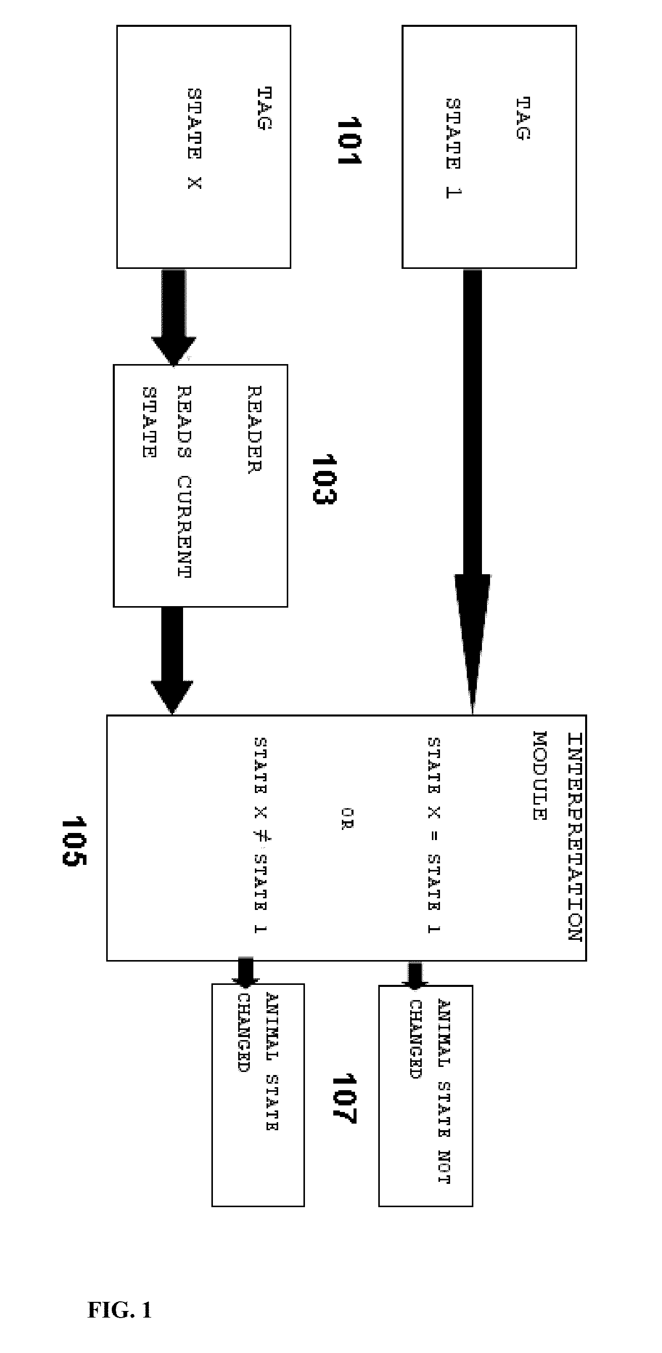
[0129]Example 1 relates to a detection system where the presence or absence of a detection tag signal is used to determine any change of state of the detection tag. This example is a binary mode example and the detection tag can only have one of two possible states i.e.: It is either activated or deactivated. It should be noted that this example cannot distinguish between a non-functioning (that is shielded) and a missing tag.

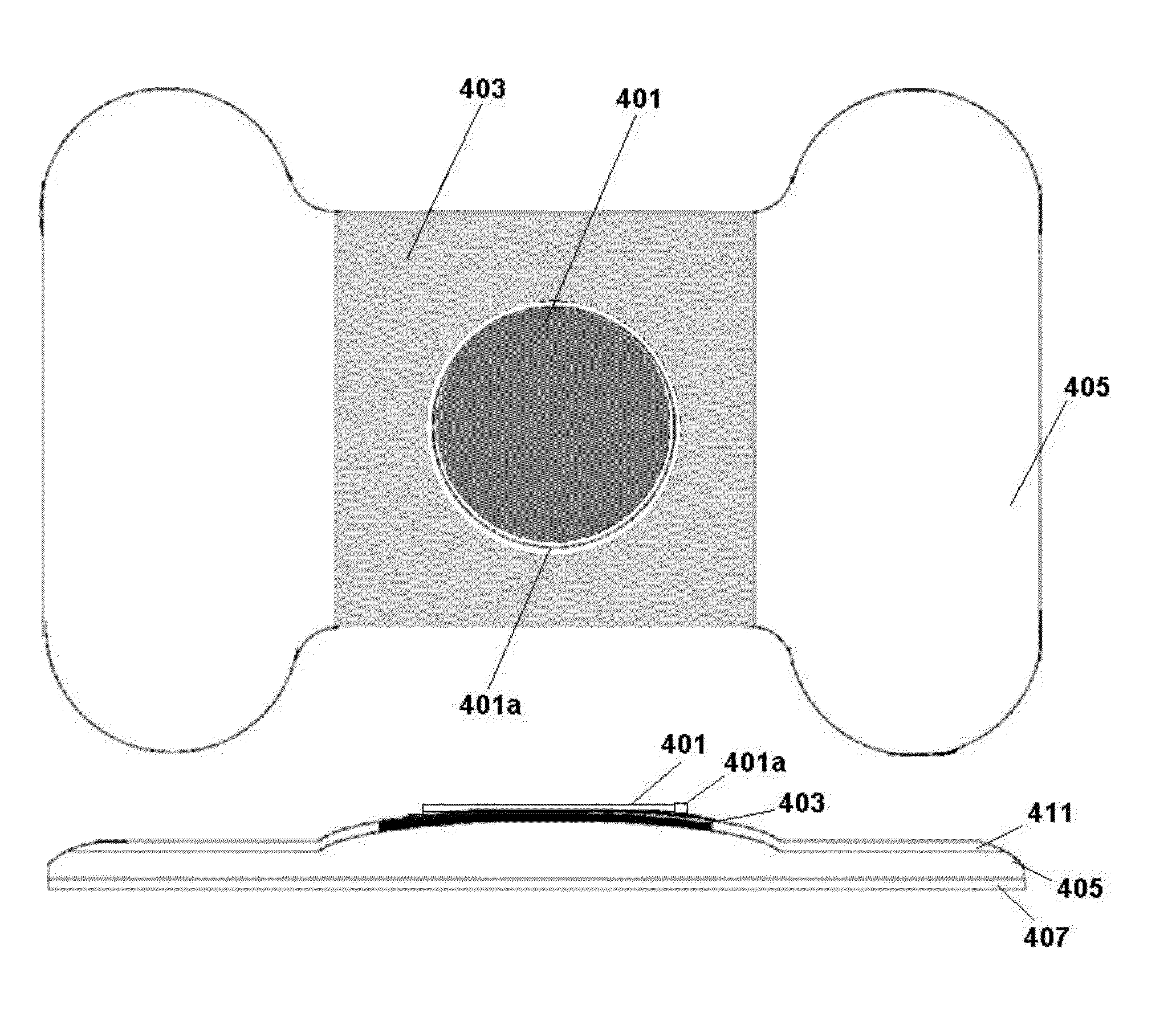
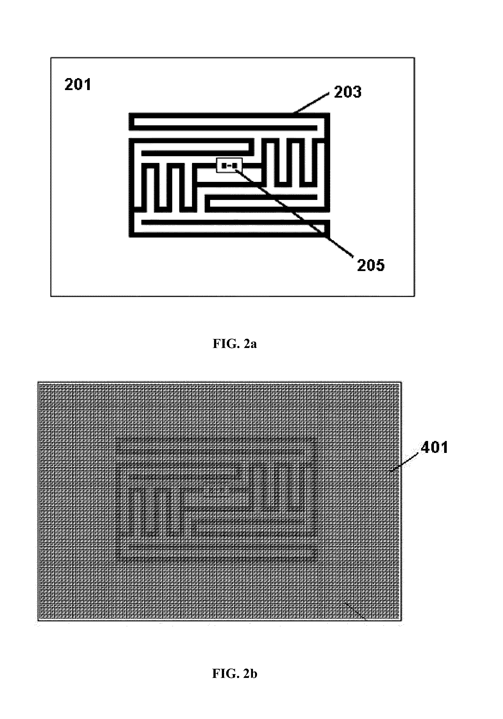
[0130]The following options can be used to indicate a status change in a detection tag which operates as a normally deactivated system:[0131]The antenna 203 of the tag (FIG. 2) is covered by a removable flood coat layer 401 and / or RF / EMF blocking circuit / loop 401a. Activation occurs when the RF / EMF blocking circuit / loop 401a is broken or damaged (partially or completely) and / or the flood coat layer is removed by an external force, thus uncovering the antenna 203 of the detection tag, making the tag detectable by a tag reader.[0132]The power supply of the tag, w...

example 2

[0147]Example 2 relates to a detection system where a change of strength of the detection tag signal is used to determine any change of state of the detection tag. This example works on a scale which means that the tag can indicate an infinite number of states and hence can allow for a more detailed interpretation of the status change of the tag. This example also allows for detecting a missing tag.

[0148]The following options can be used to indicate a status change in a detection tag which incorporates changing its signal strength when a status change occurs.[0149]The antenna 203 of the tag is partially shielded by a conductive or RF absorbent flood coat layer or an RF / EMF blocking circuit / loop. Partial damage or removal of the layer by an external force will increase the strength of the signal. The strength of the signal can thus be used to interpret the amount of layer / loop removed or still present, indicating the amount of activity that led to the current state.[0150]The antenna ...

example 3

[0151]Example 3 relates to a detection system where a change in the operational frequency of the tag is used to determine any change of state of the detection tag (i.e.: the altered characteristic of the electronically transmitted signal of the tag is a change in frequency range within which the tag becomes readable). This example is a binary mode example which means that the detection tag can only indicate any one of a set of predefined states i.e.: each state is at a specific frequency. This example can detect a missing tag since a signal must always be present in any state.

[0152]The following options can be used to indicate a status change in a detection tag which utilizes a frequency change to indicate a status change.[0153]The antenna 203 of the detection tag is shaped so that its virtual length enables coupling with the tag reader at a specific frequency range. Modifying the virtual length of the antenna changes this frequency range. The tag reader can scan through a range of ...


PUM


Abstract

A detection tag and apparatus for the detection of the reproductive status of animals, or for assisting in the drafting of selected animals. The detection tag is capable of electronically transmitting a signal. Tags for detecting the reproductive status of an animal have a first surface that is affixable to the hide of an animal and a second and opposite surface which includes abradable material. Such detection tags are configured such that removal of some or all of the abradable material alters the ability of the detection tag to transmit a signal electronically or alters a characteristic of the electronically transmitted signal. A tag reader is used to read the signal from the tag. The detection tag can include an RF/EMF blocking circuit/loop and/or removable flood coat layer which is damaged/removed partially or completely during mounting of the animal allowing the tag to indicate a status change.

Description

FIELD OF THE INVENTION[0001]The invention relates to an improved detection system. More particularly it relates to an improved detection system for detecting the reproductive state of animals, or for detecting animals that have been selected for a particular reason.BACKGROUND OF INVENTION[0002]The detection of the reproductive status of animals is highly desirable for farmers. It is especially desirable for a farmer to know when individual cows in a herd are ‘in heat’. The early detection of cows in heat allows the farmer to improve his livestock by selective breeding and to better plan his business operations. This can be achieved by mating selected animals, using artificial insemination or any other suitable method. When using any of these methods, it is necessary to determine accurately and reliably when cows are in heat so that the cows in heat could be singled out and inseminated. The heat cycle of cows is active only for a short period of time and hence detection and inseminat...

Claims


Application Information

Patent Timeline
Patent Type & Authority Applications(United States)
IPC IPC(8): A01K29/00A61B17/425
CPCA01K11/00A01K11/006A61B17/425G06K19/07327G06K19/07749A01K29/005A61D17/002
Inventor FOLKERS, CHRISTIANUS JOHANNES
Owner FIELDTECH
Why Eureka
Try Eureka