Capacitive sensing system configured for using heating element as antenna electrode

a capacitive sensing and heating element technology, applied in the direction of instruments, pedestrian/occupant safety arrangements, vehicular safety arrangements, etc., can solve problems such as measurement resolution problems, and achieve the effect of convenient connection

Active Publication Date: 2013-04-25
IEE INT ELECTRONICS & ENG SA
View PDF3 Cites 60 Cited by
  • Summary
  • Abstract
  • Description
  • Claims
  • Application Information

AI Technical Summary

Problems solved by technology

This is problematic in terms of measurement resolution.

Method used


Image

  • Capacitive sensing system configured for using heating element as antenna electrode
  • Capacitive sensing system configured for using heating element as antenna electrode
  • Capacitive sensing system configured for using heating element as antenna electrode

Examples


Embodiment Construction

[0028]In the following, it will be assumed that the heating current is direct current (DC) and that the capacitive measurement uses alternating current (AC) at a certain frequency. This is insofar a simplification that transient states (e.g. switching on / or off of the heating current), noise and parasitic currents are not taken into account. It should also be noted that the heating current need not be direct current in the strictest sense: it may be variable, but on a long time-scale, so as not to interfere with the current used for the capacitive measurement. For sake of simplicity, we will use “DC” to designate slowly varying or constant signals. The capacitance measurement network preferably operates at frequency selected in the range from about 50 kHz to about 10 GHz, more preferably in the range from about 50 kHz to about 30 MHz.

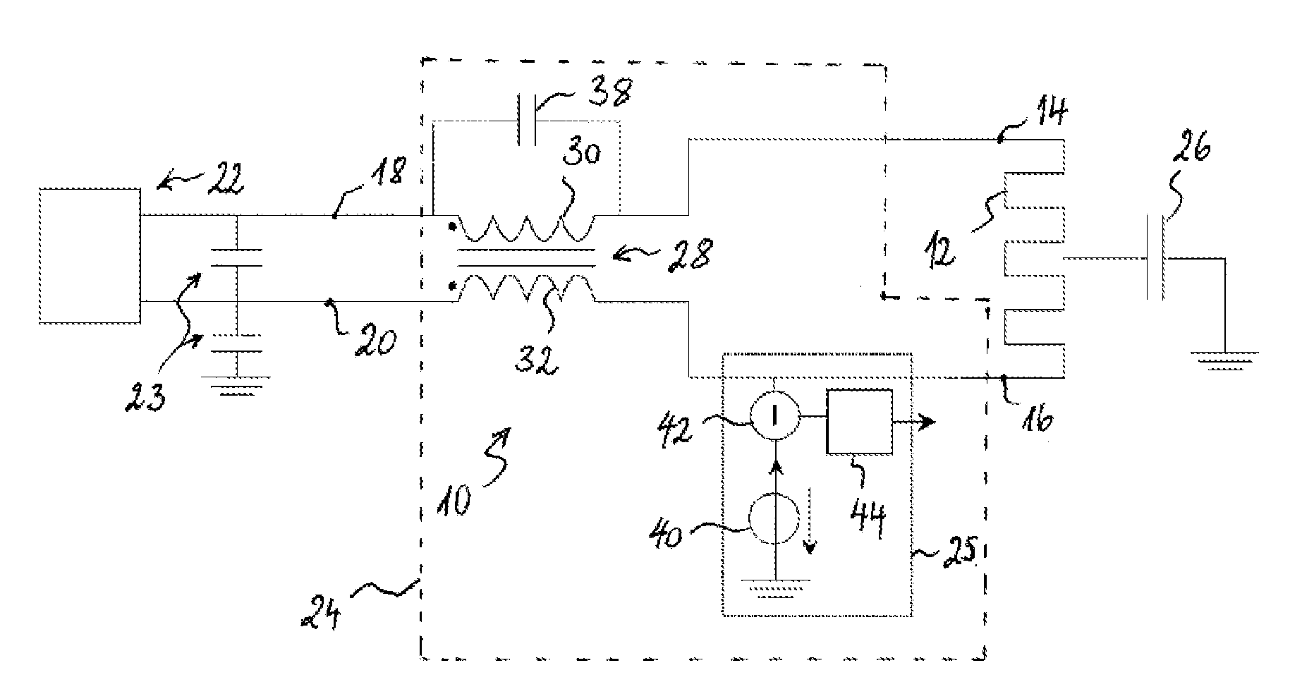
[0029]FIG. 1 shows a combined heating and capacitive sensing system 10 according to a preferred embodiment of the invention. The combined system 10 com...


PUM


Abstract

A capacitive sensing system for a heating element comprises a capacitive detector connectable to the heating element and a common mode choke for connecting the heating element with a heating current supply. The detector drives an alternating current into the heating element and produces an output depending on the capacitive load, which the alternating current is subject to. Depending on the object sensed, the load varies in a range between a minimum and a maximum value. The choke represents an inductive load in parallel of the capacitive load. The capacitive load and the inductive load contribute to a complex impedance dominated by the inductive load. A compensation capacitor arranged parallel to the choke represents an additional capacitive load also contributing to the complex impedance. The compensation capacitor is dimensioned such that the sum of additional capacitive load and maximum value amounts to at least 50% of the inductive load.

Description

TECHNICAL FIELD[0001]The present invention generally relates to a capacitive sensing system that can use a heating element as its antenna electrode. A capacitive sensing system as proposed herein may e.g. be used for detecting the absence or presence of an occupant on an occupiable item, which might be a vehicle seat, a hospital bed etc., or for detecting a driver's hand on the steering wheel.BACKGROUND ART[0002]A capacitive sensor, called by some electric field sensor or proximity sensor, designates a sensor, which generates a signal responsive to the influence of what is being sensed (a person, a part of a person's body, a pet, an object, etc.) upon an electric field. A capacitive sensor generally comprises at least one antenna electrode, to which is applied an oscillating electric signal and which thereupon emits an electric field into a region of space proximate to the antenna electrode, while the sensor is operating. The sensor comprises at least one sensing electrode at which ...

Claims


Application Information

Patent Timeline
Patent Type & Authority Applications(United States)
IPC IPC(8): H05B1/00G01R27/26
CPCB60N2/5685B62D1/046B60R21/0154B60N2/002B60R21/01532B62D1/065
Inventor VIRNICH, MICHAELHOYER, DAVIDTHINNES, MARTINPUETZ, MICHAELMEYERS, THOMASLAMESCH, LAURENT
Owner IEE INT ELECTRONICS & ENG SA
Why Eureka
Try Eureka