Zoom lens

a zoom lens and zoom technology, applied in the field of zoom lenses, can solve the problems of inability to correct the aberration of near infrared light, the optical system is not suitable as an optical system, and the obtained image is out of focus

Inactive Publication Date: 2013-04-25
TAMRON
View PDF3 Cites 5 Cited by
  • Summary
  • Abstract
  • Description
  • Claims
  • Application Information

AI Technical Summary

Benefits of technology

[0012]It is an object of the present invention to at le...

Problems solved by technology

In general, in an optical system designed to use visible light, chromatic aberration especially occurs in the near infrared range and when imaging is performed at night in the near infrared range, the obtained images are out of focus.
In addition, aberration of near infrared light is not corrected.
Therefore, the optical system is not suitable as an optical system to be used for a surveillance camera.
H6-138390 is compact having an overall length that is short, the optical system has a large F number, despite being a wide angle lens, and does not sufficiently correct chromatic aberration.
Therefore, the optical system has a problem in terms of imaging performance with respect to near infrared light.
In addition, the distance from the aperture stop to t...

Method used


Image

  • Zoom lens
  • Zoom lens
  • Zoom lens

Examples


first embodiment

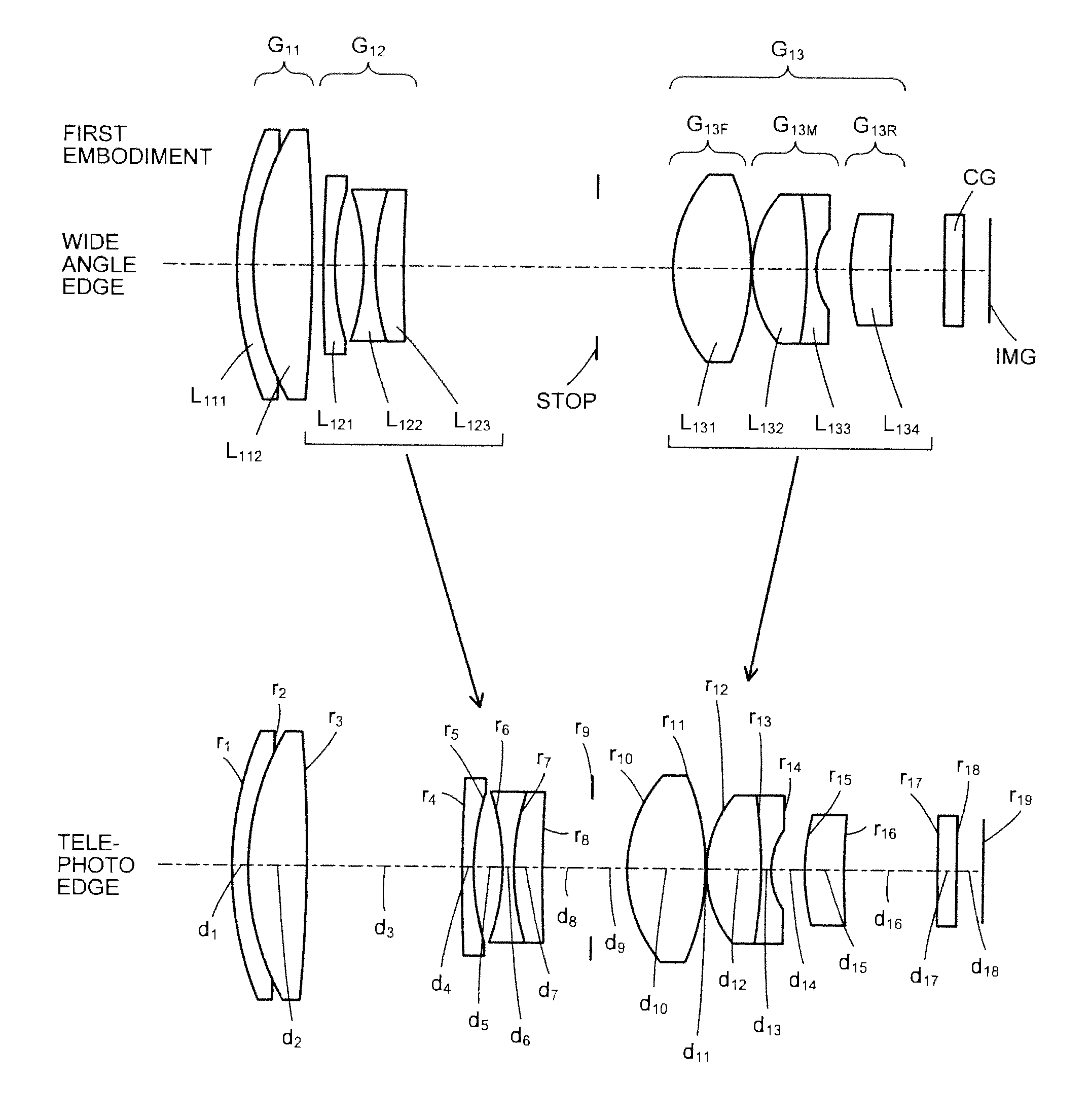
[0054]FIG. 1 is a cross sectional view (along the optical axis) of the zoom lens according to a

[0055]The zoom lens includes sequentially from a non-depicted object (object side), a first lens group G11 having a positive refractive power, a second lens group G12 having a negative refractive power, an aperture stop STOP prescribing a given aperture, and a third lens group G13 having a positive refractive power. Between the third lens group G13 and an image plane IMG, a cover glass CG is disposed. The cover glass CG is disposed as necessary and may be omitted accordingly. At the image plane IMG, the light receiving surface of a solid state image sensor, such as a CCD and CMOS, is disposed.

[0056]The first lens group G11 includes sequentially from the object side, a negative lens L111 and a positive lens L112. The negative lens L111 and the positive lens L112 are cemented.

[0057]The second lens group G12 includes sequentially from the object side, a negative lens L121, a negative lens L12...

second embodiment

[0062]FIG. 3 is a cross sectional view (along the optical axis) of the zoom lens according to a The zoom lens includes sequentially from a non-depicted object (object side), a first lens group G21 having a positive refractive power, a second lens group G22 having a negative refractive power, the aperture stop STOP prescribing a given aperture, and a third lens group G23 having a positive refractive power. Between the third lens group G23 and the image plane IMG, the cover glass CG is disposed. The cover glass CG is disposed as necessary and may be omitted accordingly. At the image plane IMG, the light receiving surface of a solid state image sensor, such as a CCD and CMOS, is disposed.

[0063]The first lens group G21 includes sequentially from the object side, a negative lens L211 and a positive lens L212. The negative lens L211 and the positive lens L212 are cemented.

[0064]The second lens group G22 includes sequentially from the object side, a negative lens L221, a negative lens L22...

third embodiment

[0069]FIG. 5 is a cross sectional view (along the optical axis) of the zoom lens according to a The zoom lens includes sequentially from a non-depicted object (object side), a first lens group G31 having a positive refractive power, a second lens group G32 having a negative refractive power, the aperture stop STOP prescribing a given aperture, and a third lens group G33 having a positive refractive power. Between the third lens group G33 and the image plane IMG, the cover glass CG is disposed. The cover glass CG is disposed as necessary and may be omitted accordingly. At the image plane IMG, the light receiving surface of a solid state image sensor, such as a CCD and CMOS, is disposed.

[0070]The first lens group G31 includes sequentially from the object side, a negative lens L311 and a positive lens L312. The negative lens L311 and the positive lens L312 are cemented.

[0071]The second lens group G32 includes sequentially from the object side, a negative lens L321, a negative lens L32...


PUM


Abstract

A zoom lens includes sequentially from an object side, a first lens group having a positive refractive power, a second lens group having a negative refractive power, an aperture stop, and a third lens group having a positive refractive power. The first lens group includes a negative lens and a positive lens. The second lens group includes sequentially from the object side, a negative lens, a negative lens, and a positive lens. The third lens group includes sequentially from the object side a front group having a positive refractive power, a middle group having a negative refractive power, and a rear group having a positive refractive power. The front group is formed by a positive aspheric lens. The middle group is includes a cemented lens formed by a positive lens and a negative lens.

Description

BACKGROUND OF THE INVENTION[0001]1. Field of the Invention[0002]The present invention relates to a zoom lens suitable for imaging apparatuses equipped with a solid state image sensor such as a charged coupled device (CCD) and a complementary metal oxide semiconductor (CMOS).[0003]2. Description of the Related Art[0004]The pixel counts of solid state image sensors equipped on imaging apparatuses such as digital cameras and video cameras continue to increase. Higher performance enabling even finer features of a subject to be seen is also demanded of optical systems used on imaging apparatuses equipped with such solid state imaging sensors and numerous optical systems developed to meet such demands have appeared (see, for example, Japanese Patent No. 2899019, and Japanese Patent Application Laid-Open Publication Nos. H6-138390, 2010-237455, and 2005-227507).[0005]High resolution imaging is also demanded of surveillance cameras to record images as evidence having high credibility for th...

Claims


Application Information

Patent Timeline
IPC IPC(8): G02B15/14
CPCG02B15/173G02B15/143105
Inventor MITSUHASHI, TAKAHIRO
Owner TAMRON
Why Eureka
Try Eureka