Rotary machine and pump driving apparatus

a technology of rotary machines and driving apparatuses, which is applied in the direction of positive displacement liquid engines, couplings, liquid fuel engines, etc., can solve the problems of increasing the distance between the bearing supporting the rotary shaft and the bearing, reducing the life of the bearing, and not being able to sufficiently shorten the shaft. , to achieve the effect of suppressing the deviation of the axis, increasing the distance, and reducing the inclination of the rotary sha

Active Publication Date: 2013-04-25
ADVICS CO LTD
View PDF10 Cites 7 Cited by
  • Summary
  • Abstract
  • Description
  • Claims
  • Application Information

AI Technical Summary

Benefits of technology

[0016]According to the above configuration, since one of the bearings is arranged at the leading end side of the rotary shaft more than the seal member, it is possible to increase a distance between the two bearings so that it is possible to further reduce the inclination of the rotary shaft Therefore,

Problems solved by technology

However, in case that the axial thicknesses of the two rotary pumps are made to be different, similarly to the pump driving apparatus of JP-A-2008-49743, the discharge load of the one rotary pump having the larger axi

Method used


Image

  • Rotary machine and pump driving apparatus
  • Rotary machine and pump driving apparatus
  • Rotary machine and pump driving apparatus

Examples


Embodiment Construction

[0023]Hereinafter, illustrative embodiments of this disclosure will be described with reference to the accompanying drawings. In the respective illustrative embodiments, the same or equivalent parts are indicated with the same reference numerals in the drawings.

First Illustrative Embodiment

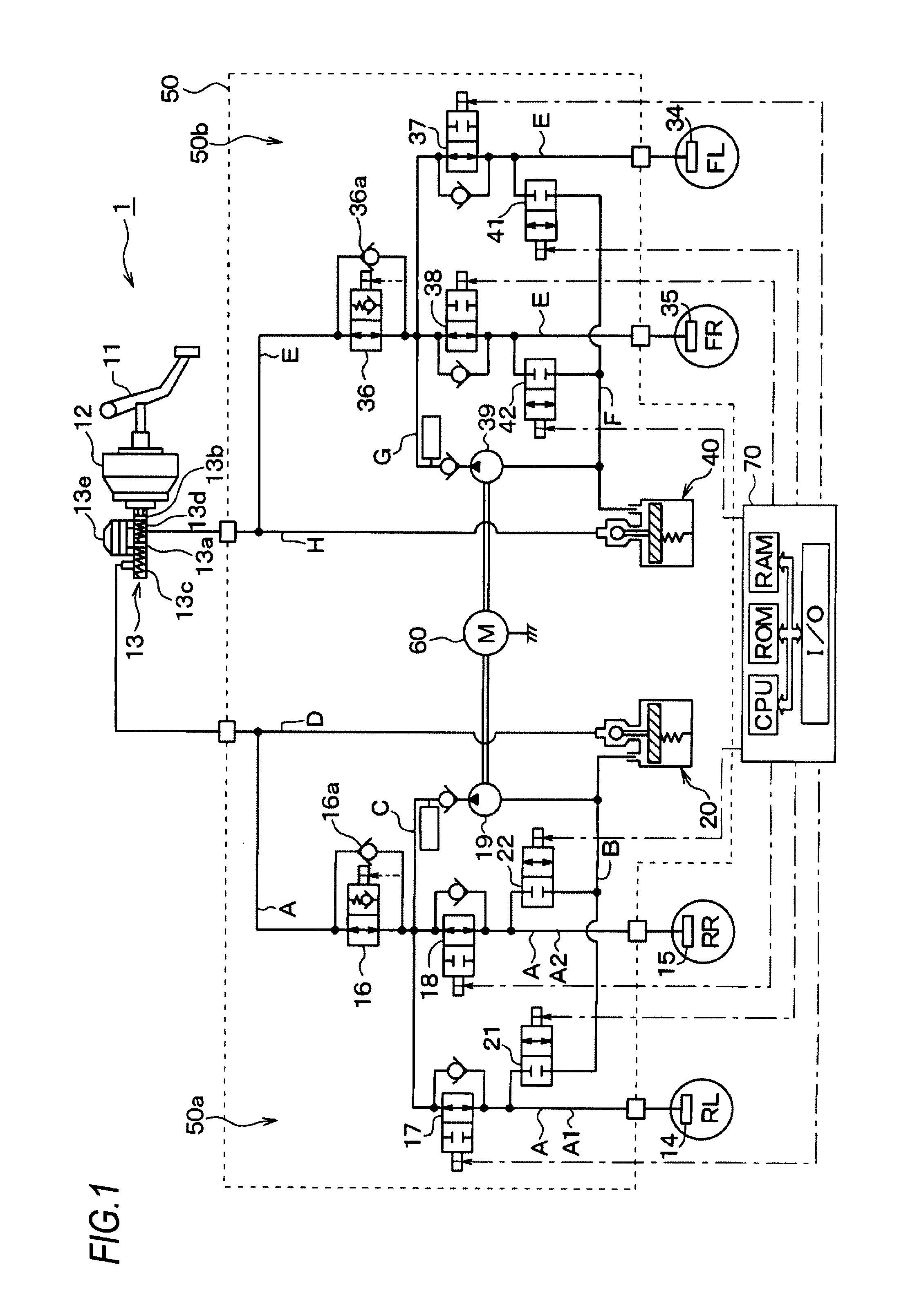
[0024]In the below, an illustrative embodiment of this disclosure shown in the drawings will be described. FIG. 1 is a schematic view illustrating a brake piping of a brake apparatus for a vehicle to which a rotary pump apparatus according to an illustrative embodiment of this disclosure is applied. A basic configuration of the brake apparatus for a vehicle is described with reference to FIG. 1. Hereinafter, it will be described as an example that the brake apparatus for a vehicle of this disclosure is applied to a vehicle configuring a hydraulic pressure circuit of a front-rear piping.

[0025]In FIG. 1, when a driver presses a brake pedal 11 serving as a brake operating member, the pressing force i...


PUM


Abstract

A rotary machine includes a rotary shaft having two driving reactive force receiving parts that are displaced in an axial direction and are applied with diametrical reactive forces having different rotation phases from driving targets as normal loads; and bearings that rotatably support the rotary shaft wherein the rotary shaft is rotated at a state where the rotary shaft is supported by the bearings to drive the driving targets via the driving reactive force receiving parts, wherein the bearings are respectively provided at both axial sides of one of the two driving reactive force receiving parts, which receives a higher normal load, and wherein a leading end side of the rotary shaft more than the other of the two driving reactive force receiving part, which receive a lower normal load lower than the higher normal load, is configured as a free end.

Description

CROSS-REFERENCE TO RELATED APPLICATION[0001]This application claims priority from Japanese Patent Application No. 2011-233088 filed on Oct. 24, 2011, the entire subject matter of which is incorporated herein by reference.TECHNICAL FIELD[0002]This disclosure relates to a rotary machine supporting a rotary shaft by a bearing, which has two driving reactive force receiving parts having different rotary phases. For example, this disclosure is appropriate for a pump driving apparatus that drives two pumps by the same rotary shaft.BACKGROUND[0003]It is known that a rotary machine supporting a rotary shaft by a bearing has two driving reactive force receiving parts having different rotary phases, and a pump driving apparatus drives two pumps by the same rotary shaft. For example, JP-A-2008-49743 discloses a pump driving apparatus. According to this pump driving apparatus, suction and discharge ports of two rotary pumps are arranged with respect to a rotary shaft so that a phase difference ...

Claims


Application Information

Patent Timeline
IPC IPC(8): F04B17/03F16D3/06F04C11/00
CPCF04C2/102F04C15/0038F04C11/001B60T8/4031B60T17/02
Inventor ANDO, KUNIHITOKATO, DAISHINAKAMURA, YUKINAGANUMA, TAKAHIROKAWABATA, TOMOAKI
Owner ADVICS CO LTD
Why Eureka
Try Eureka