
Apparatus for avoiding deposits on optical components in the laser sintering process

a technology of optical components and sintering process, which is applied in the direction of additive manufacturing process, electric/magnetic/electromagnetic heating, manufacturing tools, etc., can solve the problems of affecting the process, releasing or vaporizing the contents of polymeric powder, and incurring considerable additional costs

Active Publication Date: 2013-04-25
EVONIK OPERATIONS GMBH
View PDF10 Cites 37 Cited by
  • Summary
  • Abstract
  • Description
  • Claims
  • Application Information

AI Technical Summary

Benefits of technology

The present invention provides a better way to make 3D objects layer by layer. The process stops vapors from cooling and sticking to sensitive parts like lenses.

Problems solved by technology

A common problem incurred with the above described conventional processes is that constituents of the polymeric powder are released or vaporized when the polymeric powders are heated.
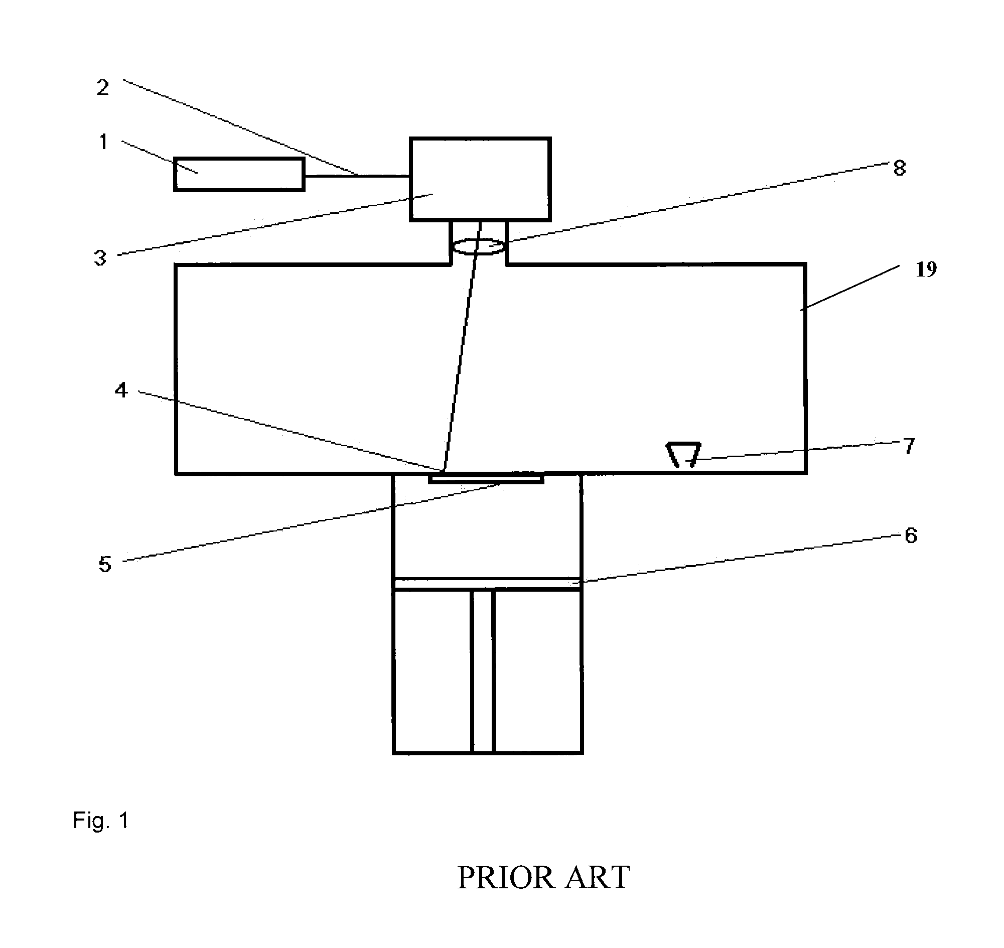
The substances or vapours which are released disrupt the process, because they condense on important components of the production apparatus, such as lenses, pyrometer or mask, and impair their function.
The content of monomers and oligomers in the polymer can be reduced, but this incurs considerable additional costs.

Method used


Image

  • Apparatus for avoiding deposits on optical components in the laser sintering process
  • Apparatus for avoiding deposits on optical components in the laser sintering process
  • Apparatus for avoiding deposits on optical components in the laser sintering process

Examples


example 1

Not According to the Invention

[0076]The construction process is carried out in an EOSINT P380 from EOS GmbH. A PA12 powder with the powder properties in Table 1 is processed. The process temperature is 170° C. The energy input from the laser is 60 mJ / mm2 (laser power 36.0 W, scan velocity 2000 mm / s, distance between irradiation lines 0.3 mm). Heavy deposits are discernible on lens and pyrometer after the end of the construction process. Amount of deposit on lens: 0.009 g. The difference between the centre and the corners of the underside of the resultant component is 0.84 mm.

example 2

Not According to the Invention

[0077]The construction process is carried out in an SPro60HDHS from 3d-systems. A PA12 powder with the powder properties in Table 1 is processed. The process temperature is 168° C. The energy input from the laser is 36 mJ / mm2 (laser power 65.0 W, scan velocity 6000 mm / s, distance between irradiation lines 0.3 mm). Heavy deposits are discernible on the lens after the end of the construction process. Amount of deposit on lens: 0.007 g. The difference between the centre and the corners of the underside of the resultant component is 0.71 mm.

[0078]In Examples 1 and 2, attempts are made to direct a stream of inert gas onto the lens in such a way that the volatile constituents cannot condense on the lens. As shown by Examples 1 and 2 not according to the invention, this is not adequately successful. The inert gas, markedly colder than the construction chamber, also serves for the cooling of the lens.

example 3

Not According to the Invention

[0079]The construction process is carried out in an EOSINT P380 from EOS GmbH. A PA6 powder with the powder properties in Table 2 is processed. The process temperature is 199° C. The energy input from the laser was 60 mJ / mm2 (laser power 36.0 W, scan velocity 2000 mm / s, distance between irradiation lines 0.3 mm). Extremely heavy deposits are discernible on the lenses and pyrometer after the end of the construction process. Amount of deposit on each lens: 0.026 g. The difference between the centre and the corners of the underside of the resultant component is 0.94 mm.


PUM

PropertyMeasurementUnit
areaaaaaaaaaaa
temperatureaaaaaaaaaa

Abstract

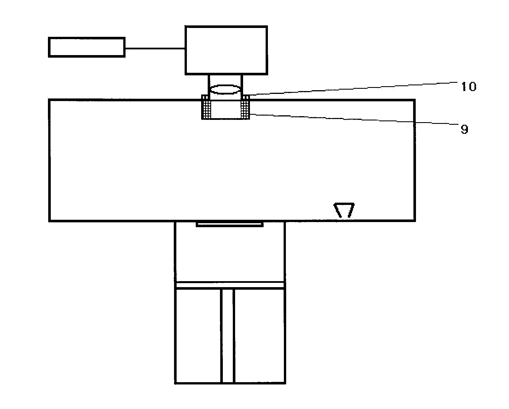
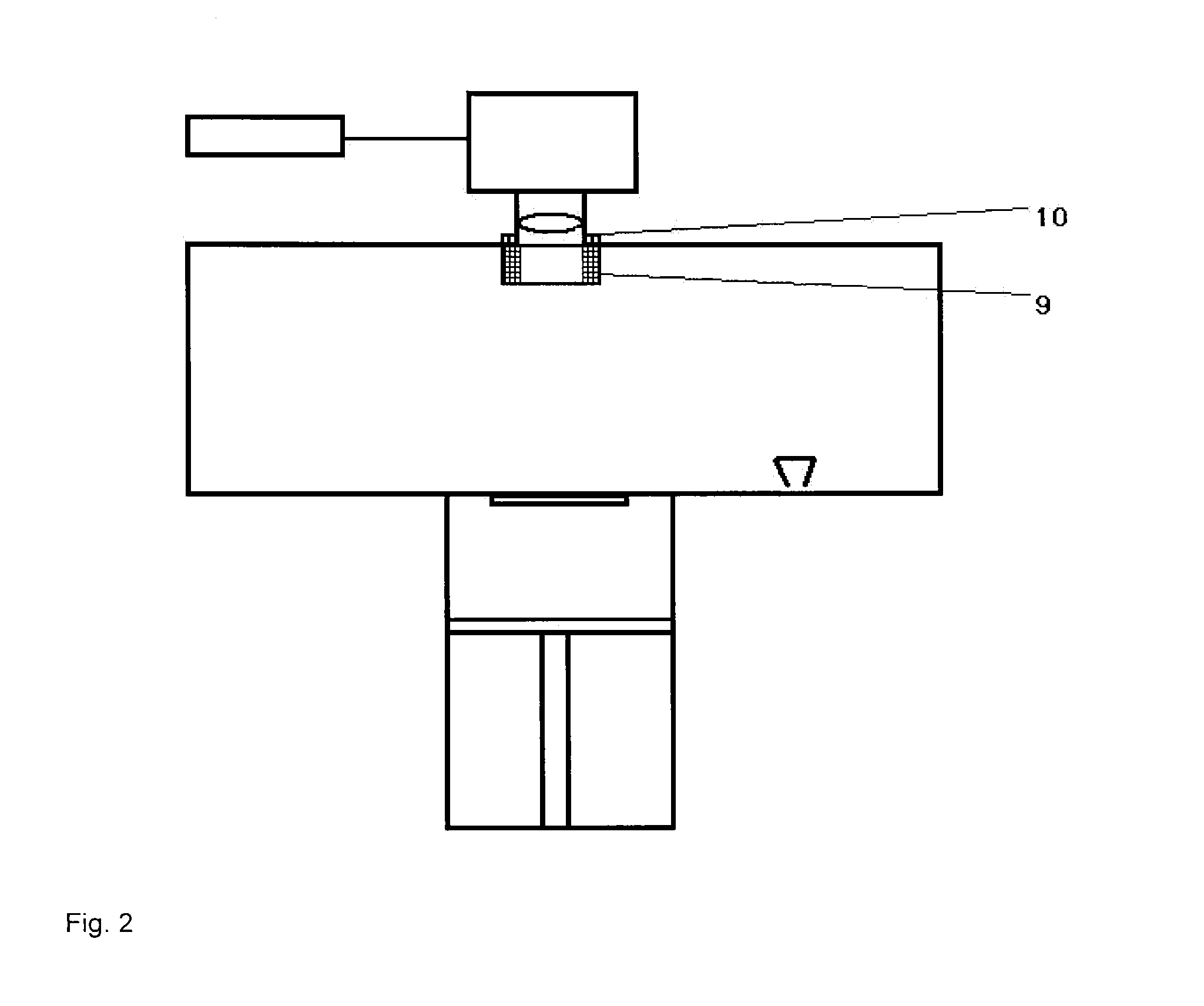
The present invention provides a process and an apparatus for the layer-by-layer production of three-dimensional objects, wherein material vapours formed during processing in the construction chamber are prevented from deposition on apparatus components by exposing the gases to deposition surfaces where the materials condense and deposit.

Description

CROSS REFERENCE TO RELATED APPLICATIONS[0001]This application claims priority to German Application No. 102011085154.2, filed Oct. 25, 2011, the disclosure of which is incorporated herein by reference in its entirety.BACKGROUND OF THE INVENTION[0002]The present invention relates to an apparatus for the layer-by-layer production of three-dimensional objects, to processes for layer-by-layer production, and also to corresponding mouldings.[0003]The rapid provision of prototypes is a task frequently encountered in very recent times. Processes which permit the rapid provision of a prototypes are described as rapid prototyping, rapid manufacturing, or as an additive fabrication process. Particularly suitable processes the rapid provision of a prototype are based on selective melting and solidification of pulverulent materials which are produced in a layer-by-layer manner through selective melting and solidification of the pulverulent material according to a pattern of the prototype object...

Claims


Application Information

Patent Timeline
Patent Type & Authority Applications(United States)
IPC IPC(8): B29C35/08B32B3/26B29C67/24
CPCB22F3/1055B29C67/0077Y10T428/24612B22F2003/1056B29C67/0085B29C64/129B29C64/153B33Y30/00B33Y10/00B29C64/245B29C64/268B29C64/371B29C64/182Y02P10/25B22F2999/00B22F12/40B22F10/28B22F12/17B22F12/70B22F10/77B22F10/32B22F12/20B22F10/68
Inventor GREBE, MAIKHESSEL-GELDMANN, SIGRIDDIEKMANN, WOLFGANG
Owner EVONIK OPERATIONS GMBH
Learn More