Mine eqipment recovery system

Inactive Publication Date: 2013-05-02
GRAHAM ROBERT WAYNE
View PDF10 Cites 4 Cited by
  • Summary
  • Abstract
  • Description
  • Claims
  • Application Information

AI Technical Summary

Benefits of technology

[0015]In at least one embodiment of the invention, a vehicle frame approximately the width of the push-beam conveyor has multiple axels along its length. These axels run transverse to the push-beam conveyor, the vehicle body. Each axel has multiple wheels upon it and these wheels are spaced to accommodate features in the push-beam conveyor section. For example, some types of push-beam conveyors have troughs in them for accommodating power cables, hydraulic cables, and other elements for servicing the high-wall mining machine, and in some cases, the push-beam conveyor sections.
[0016]The surface control station includes many components to allow the system a high level of independent operation. As a foundation, all of the other components of the surface control station are located on a wheeled chassis. In some embodiments, this wheeled chassis may be a trailer. This wheeled chassis is highway ready with all required safety features as well as a suitable hitch when necessary, such as a fifth wheel type hitch, for connecting to a highway vehicle. The wheeled chassis also has stabilizing capabilities, such as outriggers, for operating at mine sites. Among the components that may be located on the wheeled chassis are: an operator station with controls and monitoring screens; an electrical generator; a hydraulic power unit; a battery charger; a transformer; circuit breakers; an air compressor; a crane; a battery charging station; a retrieval winch; an electric welder; and an optical alignment device, such as a laser alignment device. A cable on the retrieval winch attaches to the recovery vehicle to retrieve it should the vehicle become disabled, and the optical alignment device provides an efficient gauge for aligning the surface control station with a respective highwall cut to keep the retrieval winch and cable effective.
[0017]Because the high-wall mining machine follows the coal seam, the path of the high-wall mining shift may vary up and down. This can cause the push-beam conveyors to fo

Problems solved by technology

When the coal to overburden ratio falls below a certain ratio, the process becomes unprofitable and strip mining ceases to be the economically preferred technique at that location.
This is considered too dangerous for the insertion of any personnel and the cutter modules are directed and operated remotely.
On occasion, the high-wall miner may become lodged in the high-wall mine shaft or some problem may arise with the push-beam conveyor back in the high-wall mine shaft.
When this occurs, personnel are not allo

Method used


Image

  • Mine eqipment recovery system
  • Mine eqipment recovery system
  • Mine eqipment recovery system

Examples


Embodiment Construction

)

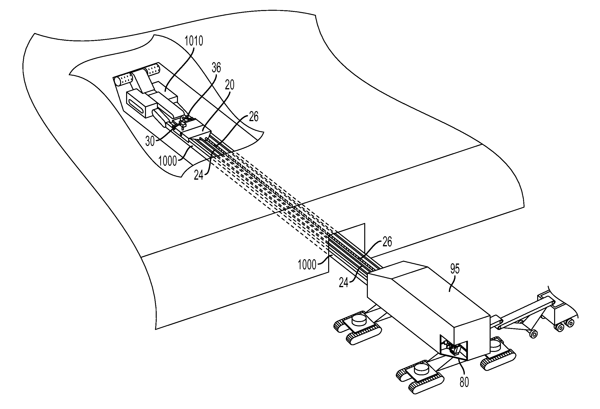
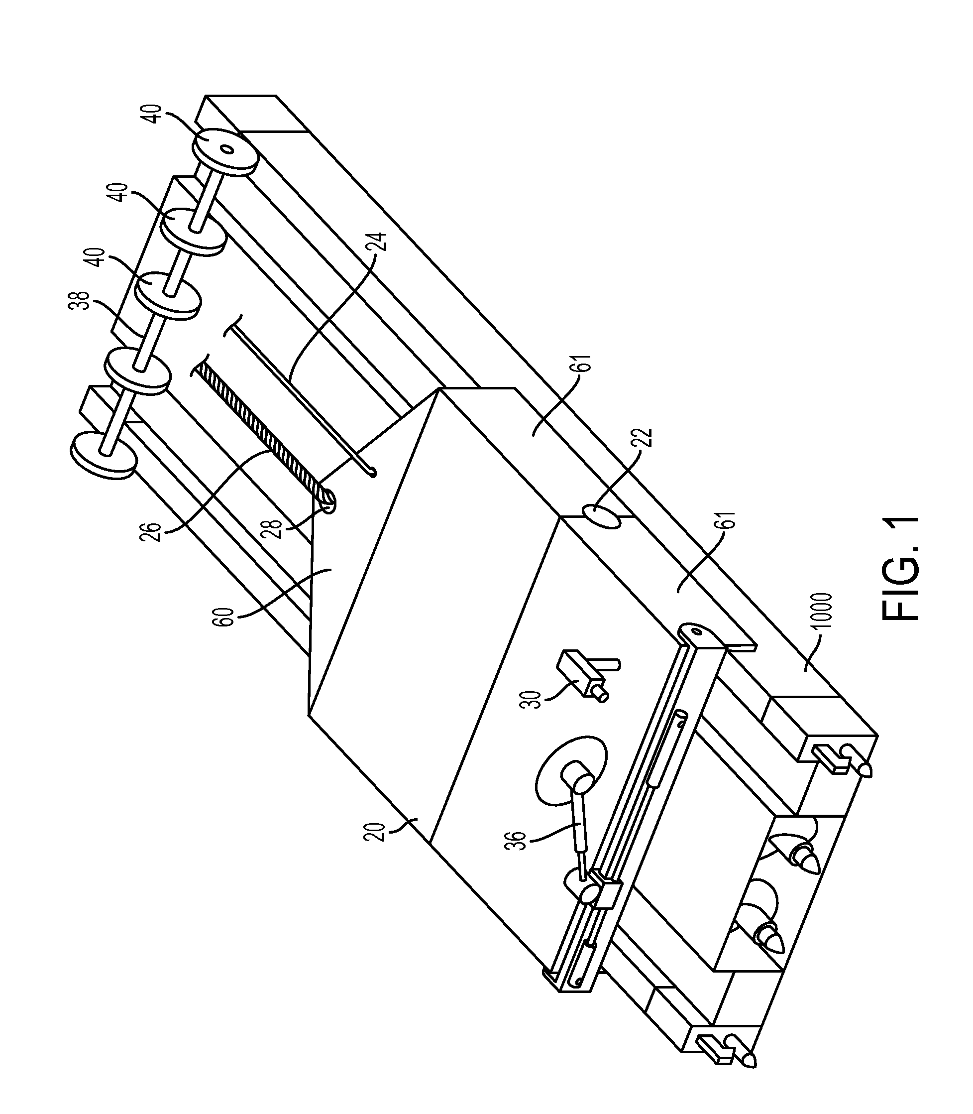
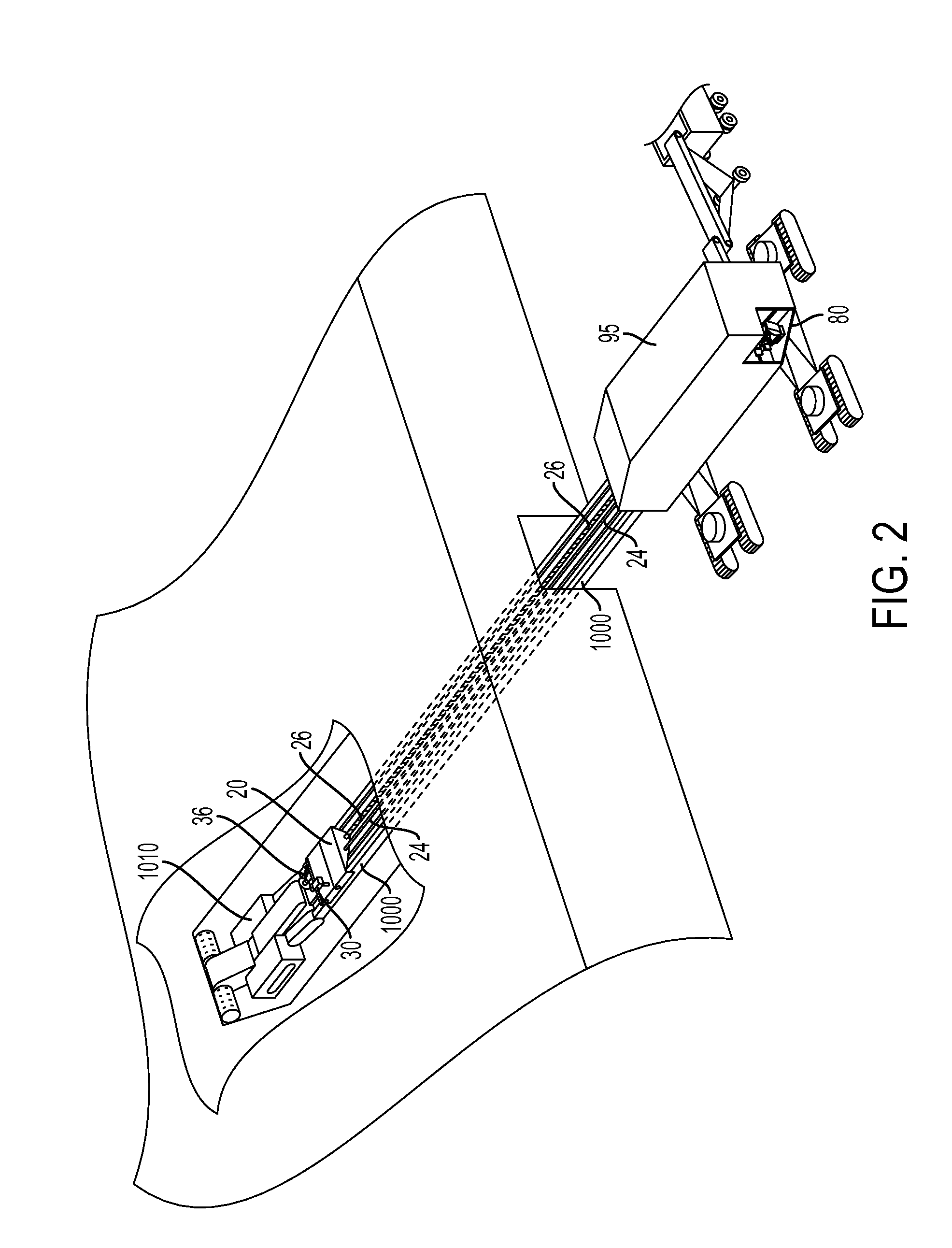
[0030]FIG. 1 is a perspective view of the equipment recovery vehicle portion 20 of the equipment recovery system 10 shown positioned on a high-wall mining push-beam conveyor 1,000. In FIG. 1 equipment recovery vehicle 20 is enclosed for the most part, and in the embodiment shown in FIG. 1 hinged toward the middle of its body. Hinge 22 in equipment recovery vehicle 20 allows equipment recovery vehicle 20 to adjust to the irregularities along the push-beam conveyor. Equipment recovery vehicle 20 is remotely operated and to that end, communication, or data, cable 24 connects at the rear equipment recovery vehicle 20. Communication cable 24 transmits instructions from a remote operator center to equipment recovery vehicle 20 and transmits information from equipment recovery vehicle 20 back to a remote operator center. Should equipment recovery vehicle 20 become disabled within the mine shaft, wire rope 26 attached to connecting point or hitch 28 on equipment recovery vehicle 20 allows ...


PUM


Abstract

An equipment recovery system for high risk environments such as high wall mine shafts has a vehicle that rides on a track including applications where a push-beam conveyor may serve as the track. The vehicle has a guide to keep it on the track and a hitch for attaching a recovery cable. The vehicle is remotely operated from outside the mine, has a power train for moving the vehicle, an implement for performing tasks, and carries an onboard power source and electrical control boxes to power and control the vehicle and implement. The vehicle may communicate with an outside operator station via an Ethernet cable and may employ and Ethernet extender for that purpose. The vehicle may have a camera to transmit video images. The vehicle may be operated from a high wall miner control center or from an operator station on a self propelled support vehicle.

Description

RELATED APPLICATIONS[0001]This application claims priority from U.S. Provisional Application No. 61 / 552,915, filed on Oct. 28, 2011. The entire disclosure contained in U.S. Provisional Application 61 / 552,915, including the attachments thereto, is incorporated herein by reference.FIELD OF INVENTION[0002]This invention is related to remote controlled vehicles for mine maintenance and service. More particularly this invention is related to a remote controlled vehicle that rides on the push beams in high-wall mining shafts.BACKGROUND OF THE INVENTION[0003]One example of an application for the apparatus of the present invention is highwall mining. During the past forty years, highwall mining has proven to be an efficient method of mining coal, or other sought after material, that would not be mined by other methods. Highwall mining is a form of mining frequently used to supplement strip mining.[0004]Strip mining is used when the sought after material deposits, such as coal, occur relativ...

Claims


Application Information

Patent Timeline
IPC IPC(8): E21F13/00
CPCE21F13/00E21F13/006E21C35/24
Inventor GRAHAM, ROBERT WAYNE
Owner GRAHAM ROBERT WAYNE
Why Eureka
Try Eureka