Monolithic photovoltaic solar concentrator

Inactive Publication Date: 2013-05-02
MORGAN INNOVATION INC
View PDF5 Cites 16 Cited by
  • Summary
  • Abstract
  • Description
  • Claims
  • Application Information

AI Technical Summary

Benefits of technology

This patent describes a special device that collects and concentrates sunlight using a special optical element. The device includes a solar cell that is directly coupled to the concentrator, which ensures that the sunlight is fully reflected and directed onto the cell. This design eliminates the need for a separate reflecting coating and ensures maximum efficiency in converting sunlight into electricity. The device can be made using a silicon or multi-junction photovoltaic cell.

Problems solved by technology

The electrical energy output from flat photovoltaic collectors is a direct function of the area of the array, thereby requiring large, expensive semiconductor substrates.
In these two referenced designs the alignment issues between the separate focusing components and reflectors in the waveguide create efficiency problems in manufacturing and in operation.
In this design, the use of mirror coated reflectors becomes not only a manufacturing and a cost issue but also an output efficiency issue since the mirror coated layer has to have a high reflectance over the local solar spectrum at each location, it creates an inherent loss and is vulnerable to degradation.

Method used


Image

  • Monolithic photovoltaic solar concentrator
  • Monolithic photovoltaic solar concentrator
  • Monolithic photovoltaic solar concentrator

Examples


first embodiment

[0042]FIG. 5 shows another embodiment of the invention having a two-sided linear or composite non-imaging solar collector apparatus 210. The solar collector apparatus 210 comprises two solar concentrators 10a, 10b described above, placed together with two image mirrored regions 2126a, 212b thereof face-to-face. Two PV cells (not shown), one for each optical element 212a, 212b, are sandwiched between the two optical elements 212a, 212b for receiving concentrated light and converting it to electrical energy. Also a double face PC cell can be used. In some embodiments heat sinks are provided in contact with the PV cells. Very thin heat sinks using the heat pipe or a Peltier device are used.

[0043]FIG. 6 is a partial, schematic, sectional view of a solar collector apparatus 200 comprising an optical element 212 according to another embodiment of the invention. The optical element 212 is sized and shaped to cause light within the optical element to experience two reflections at the stepp...

eighth embodiment

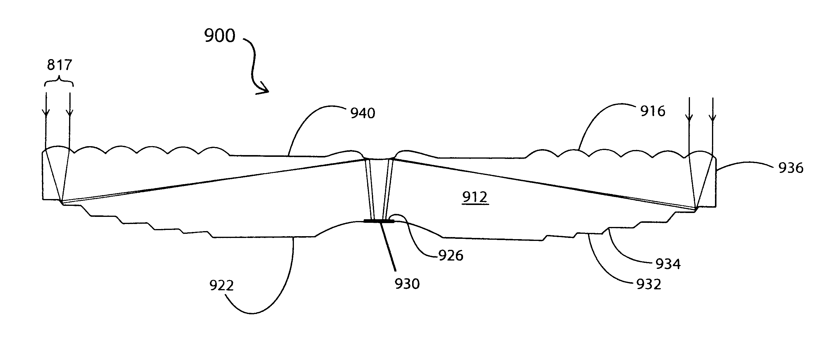
[0049]FIG. 12 is a schematic, sectional view of a circular low concentration solar collector apparatus 800 comprising an optical element 812 and a horizontally-oriented PV cell 830 according to the invention, with selected light beams 17 shown for the purpose of illustration. The optical element 812 provides low concentration since the ratio of the collection area (first surface 814) to the exit surface (in the form of light receiving region 826) is low.

[0050]The shape of the focusing elements of embodiments according to the invention may be hyperbolic, parabolic, spherical, aspherical, parabolic, elliptical or any free-form. Likewise, the shape of the light reflecting steps may be straight, curved, elliptical, parabolic, hyperbolic or any free-form.

[0051]The dimensions of the optical element will depend on a number of factors including the size and shape of the focusing elements, manufacturing tolerances, and whether the element is linear or circular.

[0052]For linear embodiments, t...


PUM


Abstract

A photovoltaic solar collector and concentrator apparatus consists of a solid, one-piece, sun light transmitting, non-imaging optical element coupled to a photovoltaic cell. The photovoltaic solar collector and concentrator has an entry surface including focusing elements and an opposed surface including uncoated reflector elements. The focused sun light is directed by the reflector elements via total internal reflection directly towards the photovoltaic cell without any reflection from the entry surface. An additional redirecting element based on total internal reflection and integral with the collector and concentrator optical element is used to couple the sunlight from the reflector elements to a photovoltaic cell positioned in plane parallel to the entry surface.

Description

CROSS-REFERENCE TO RELATED APPLICATION[0001]This application claims the benefit of U.S. provisional application No. 61 / 354,039, filed Jun. 11, 2010, and U.S. provisional application 61 / 374,499, filed Aug. 17, 2010, under 35 U.S.C.s. 119(e), which applications are herein incorporated by reference.FIELD OF THE INVENTION[0002]The present invention relates to concentrating photovoltaic solar energy collection apparatus. More particularly this invention relates to a low concentration solar energy collection photovoltaic apparatus using a light guide based on total internal reflection.BACKGROUND OF THE INVENTION[0003]Photovoltaic (PV) solar energy collection apparatus are used to generate electric power from solar energy. Flat panel collectors generally include PV cell arrays formed on semiconductor substrates (e.g., monocrystalline silicon, polycrystalline silicon or thin-films such as cadmium telluride). The electrical energy output from flat photovoltaic collectors is a direct function...

Claims


Application Information

Patent Timeline
IPC IPC(8): H01L31/0232
CPCH01L31/0543Y02E10/52H01L31/0547H01L31/02327
Inventor MYRSKOG, STEFAN
Owner MORGAN INNOVATION INC
Why Eureka
Try Eureka