Water faucet

a water faucet and faucet technology, applied in mechanical equipment, transportation and packaging, valve types, etc., can solve the problems of high-speed spraying, water sputtering, and the faucet type cannot dynamically handle changes, and achieve the effect of easy and convenient rotation and adjustmen

Active Publication Date: 2013-05-02
LIU XIONGHUI
View PDF0 Cites 9 Cited by
  • Summary
  • Abstract
  • Description
  • Claims
  • Application Information

AI Technical Summary

Benefits of technology

[0005]An object of this invention is to provide a kind of faucet to users who can control the adjustment of the water flow. With this mode of operation, water flow can be synchronized to convert its water resistance, adjust the velocity of flow, and regulate the applicable water shape. Within the water supply pressure for the range of 0.1˜0.35 MPa, users can freely adjust and compensate for changes of the water pressure. When using stepless adjustment, users can get 1.5 to 9 liters of water consumption per minute.
[0007]In order to allow users to easily and conveniently rotate and adjust the flow-adjusting positioning screw 6, a internal screw nut 15 is firmly implanted in the hollow inner circular tube wall 14 at the back-end of the main body of the water faucet 1. The bore diameter of the screw is smaller than the bore diameter of the hollow inner circular tube wall 14 at the back-end of the main body of the water faucet 1, from which a screw thread lock axis can be screwed in and its backward and forward moving distance is stopped at the back-end of the hollow flow regulating valve 8. The back-end of the flow-adjusting positioning screw 6 can serve as the turning handle.

Problems solved by technology

The vast majority of water wasting is closely related to the improper use of water faucets in the reality of production and living, and such improper use is caused by the unreasonable structure of the faucet.
However, such small flow high-speed spraying cannot solve the problem of large flow faucets which causes water sputtering.
However, the main defect is that this kind of faucet cannot dynamically handle changes which affect the flow resistance associated with good water pressure and effluent, flow rate, water conflicts and water foaming.

Method used


Image

  • Water faucet
  • Water faucet
  • Water faucet

Examples


Embodiment Construction

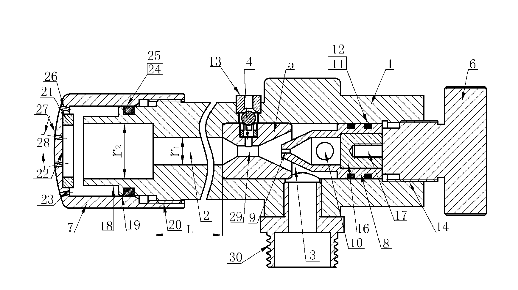
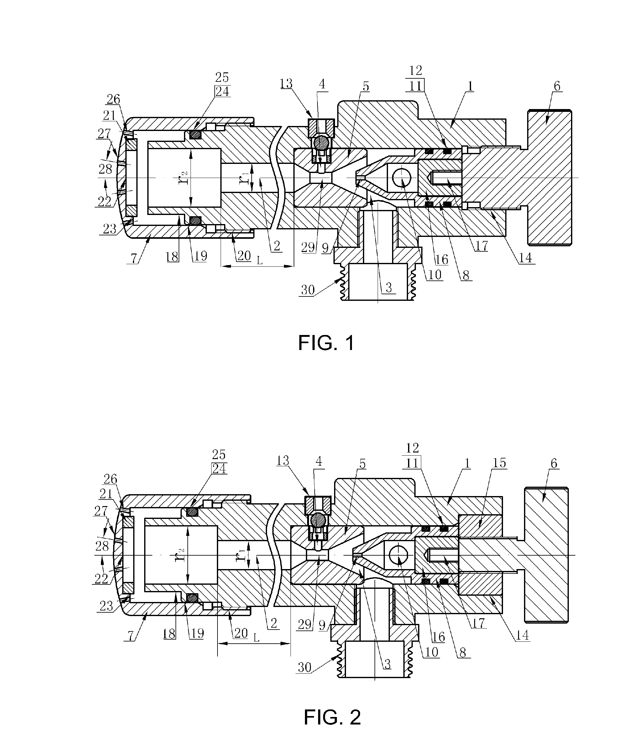
[0012]The following description, combined with the drawings, provide details of the structure and mode of use of the water faucet according to embodiments of the present invention.

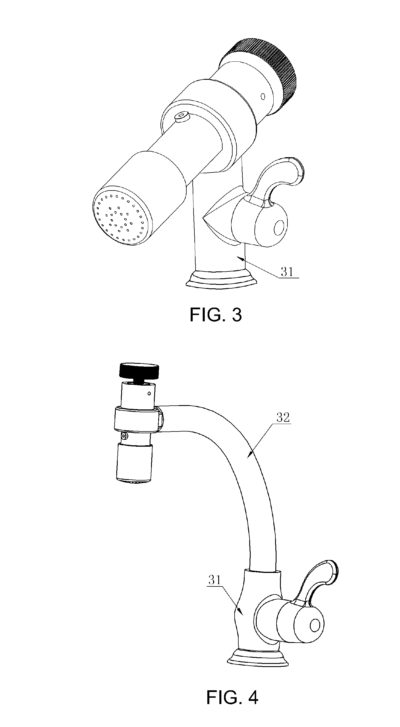
Elements of the Figures: 1main body of the water faucet 2water outlet channelLwater outlet channel wall lengthrlwater outlet channelbore diameterr2water outlet channel end 3water inlet channelbore diameter 4vent hole 5micro flow ejector 6flow-adjusting positioning screw 7adjustable shroud 8hollow flow regulating valve 9spray / ejecting orifice10water inlet / outlet hole11seal groove12seal ring13air inlet check valve14hollow inner circular tube wall15internal screw nut16seal fixed block17process control screw hole18minor diameter19pitch diameter20major diameter21ring gasket22inner ring surface23external ring surface24groove25seal ring26plughole27shroud surface28plughole angle29jet hole30external threaded coupling31inflow switch tube socket32water pipe

[0013]As it is shown in FIG. 1, the main body of the water fa...


PUM


Abstract

Disclosed is a water faucet, in which a main body (1) is composed of a water outlet channel (2) and a water inlet channel (3), with a micro flow ejector (5) having a vent hole (4) fitted between the water outlet channel (2) and the water inlet channel (3), a flow-adjusting positioning screw (6) fitted on a hollow inner circular tube wall (14) behind the micro flow ejector (5), between the micro flow ejector (5) and the flow-adjusting positioning screw (6) there being fitted a hollow flow regulating valve (8) which is T shaped at the rear portion and cone shaped at the head portion; wherein the cone-shaped head portion of the hollow flow regulating valve (8) is provided with an ejecting orifice (9), the small cylindrical tube wall of the hollow flow regulating valve (8) is provided with more than one water inlet / outlet hole (10), and an air inlet check valve (13) is placed in the vent hole (4) of the micro flow ejector (5). By using the water faucet with the above-mentioned structure of the present application, users are able to conveniently control and regulate the flow rate of water consumption at will, to obtain a water quality activated by highly effective oxygenation during water utilization, with a water supply amount between 1.5 liters and 9 liters per minute under a water supply pressure range of 0.1 MPa to 0.35 MPa.

Description

FIELD OF INVENTION[0001]The present invention relates to a water faucet, and in particular, to a water faucet with an improved water device structure to a tap water supply.BACKGROUND[0002]The vast majority of water wasting is closely related to the improper use of water faucets in the reality of production and living, and such improper use is caused by the unreasonable structure of the faucet. In order to fundamentally realize scientific water conservation, it is necessary to thoroughly improve the structure of existing faucets. At present, there are two types of water-saving faucets / taps: one is a flow-limiting and pressure-regulating spraying water nozzle. It uses the fluid continuity principle and conservation of energy principle. In the water exit of the faucet, there is a fixed hole choke device to cause the small water flow to realize a high-speed jet flow and spray the atomized water, and due to the high flow impact of the water there is an increase in the efficiency of decon...

Claims


Application Information

Patent Timeline
Patent Type & Authority Applications(United States)
IPC IPC(8): E03C1/04
CPCB05B1/3013B05B7/0425E03C2001/026E03C1/084B05B7/0483Y10T137/9464
Inventor LIU, XIONGHUI
Owner LIU XIONGHUI
Why Eureka
Try Eureka