Position detecting device
- Summary
- Abstract
- Description
- Claims
- Application Information
AI Technical Summary
Benefits of technology
Problems solved by technology
Method used
Image

Examples
first embodiment
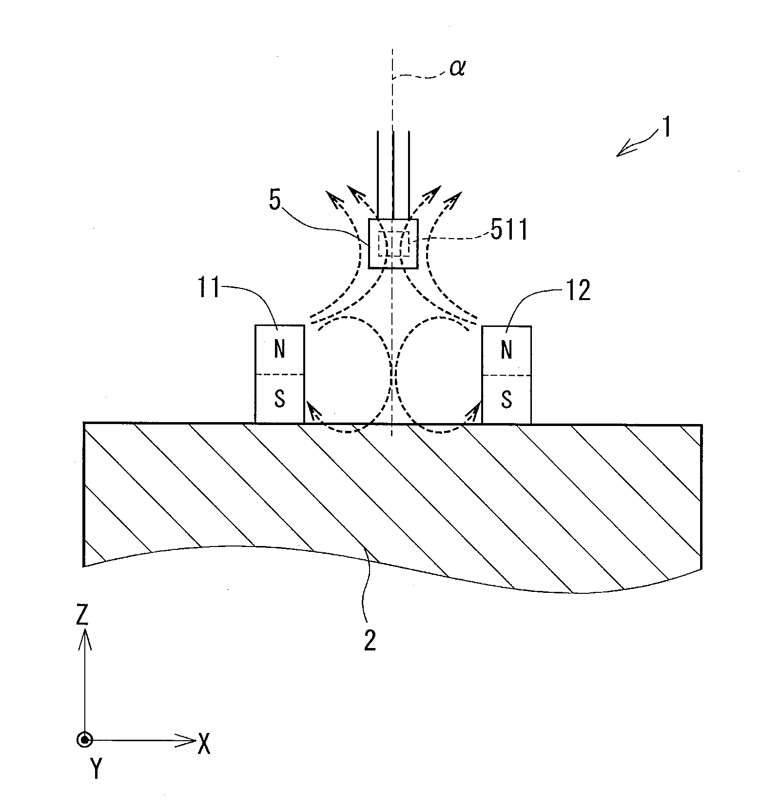
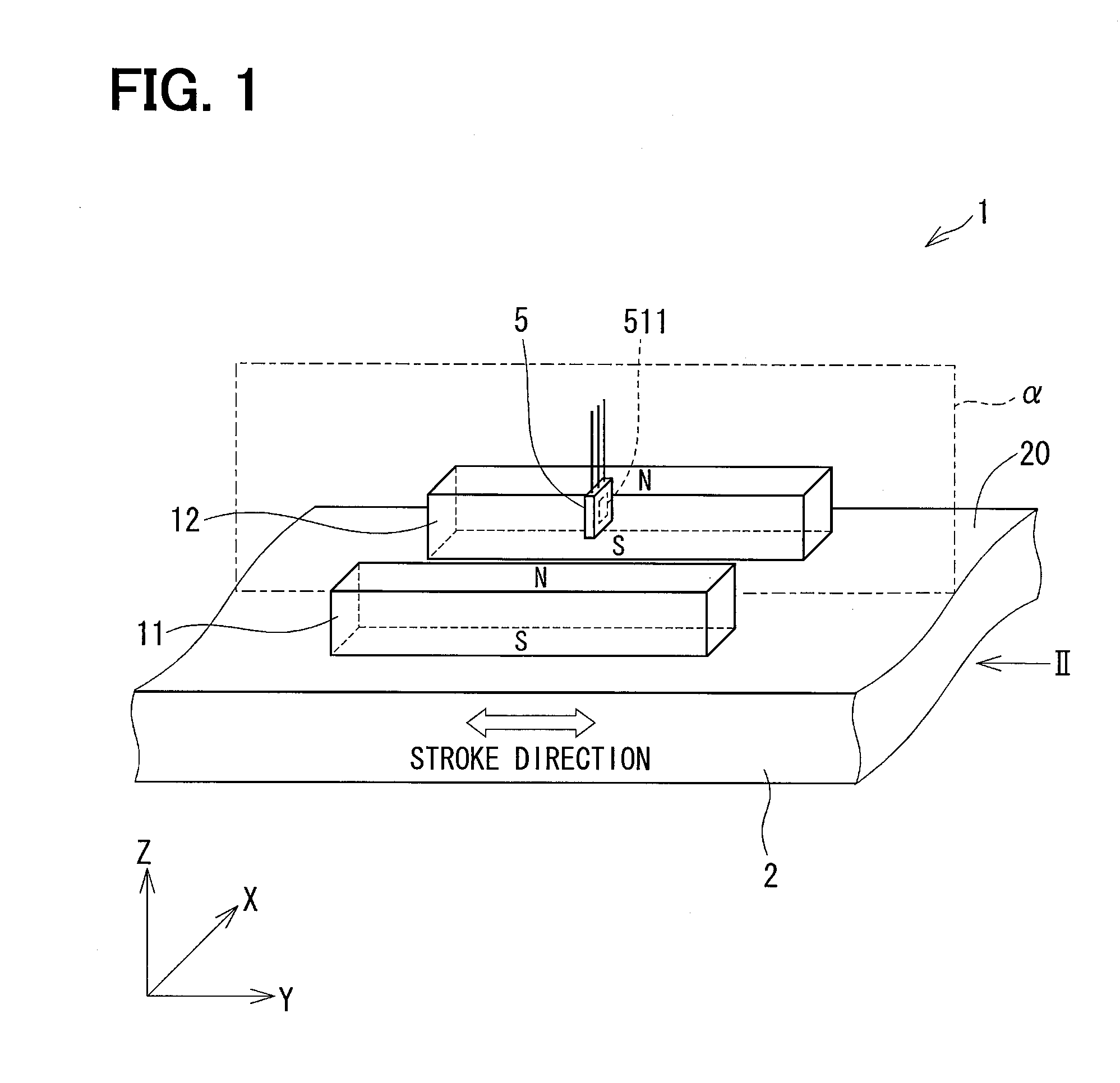
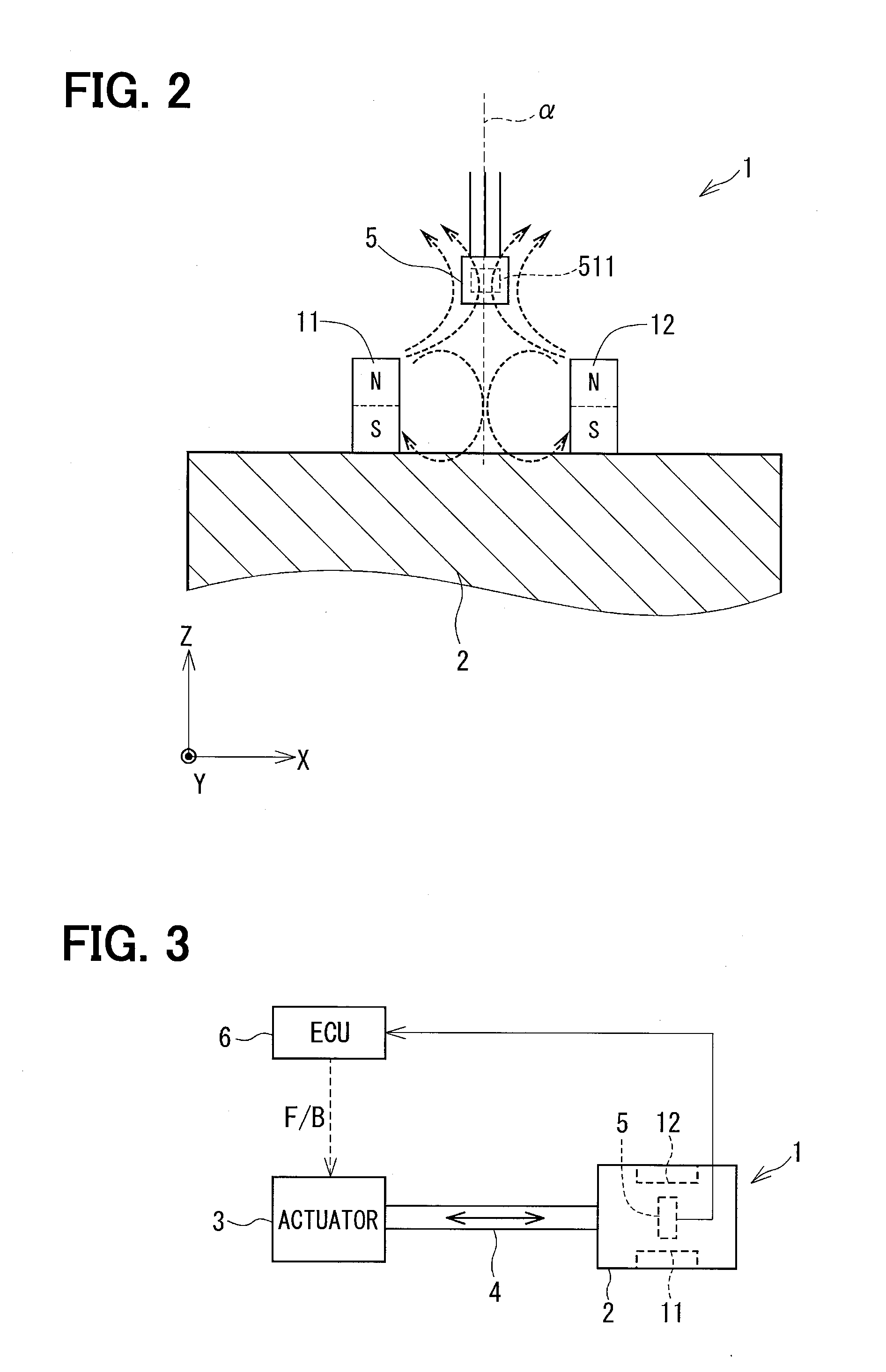
[0048]A position detecting device 1 of a first embodiment of the present disclosure will be explained with reference to FIGS. 1 to 7. The position detecting device 1 is applied to a stroke detecting portion for a transmission apparatus, an acceleration pedal, a brake pedal for a vehicle, so as to detect a position of a movable member thereof. One of examples is shown in FIG. 3. In FIG. 3, a movable member 2 is connected to a stroke portion 4 of an actuator (linear actuator) 3 and movable in a linear direction (a stroke direction) as indicated by an arrow in the drawing. A first magnet 11 (a first magnetic-field generating member) and a second magnet 12 (a second magnetic-field generating member) are provided in the movable member 2.
[0049]A hall IC 5 (a magnetic detecting member) is provided in the position detecting device 1 in such a way that the hall IC 5 moves relative to the movable member 2. The hall IC 5 outputs a signal depending on density of magnetic flux passing through a ...
second embodiment
[0072]A second embodiment of the present disclosure is shown in FIGS. 8 to 11.
[0073]In the second embodiment, the N-pole of each magnet 11 and 12 is formed at the lower side of the magnet (the movable member side), while the S-pole of each magnet 11 and 12 is formed at the upper side of the magnet (opposite to the movable member side).
[0074]As shown in FIGS. 10A and 10B, a magnetic field of the S-pole of the first magnet 11 and a magnetic field of the S-pole of the second magnet 12 rebel against each other. Such an area (a Y-parallel area) is formed in a space more remote from the movable member 2 in the direction of the Z-axis than the first and second magnets 11 and 12, in which directions of the magnetic fields are in parallel to the Y-axis, when viewed in the direction of the Z-axis.
[0075]Since the S-pole of the first magnet 11 as well as the S-pole of the second magnet 12 is formed at a position remote from the movable member 2 in the direction of the Z-axis, it is suppressed t...
third embodiment
[0080]A third embodiment of the present disclosure is shown in FIGS. 12, 13A to 13C and 14A to 14C. In a position detecting device of the third embodiment, a base plate 21 is provided between the first and the second magnets 11 and 12. The base plate 21 is made of non-magnetic material, such as metal, resin or the like. A pair of through-holes 22 extending in a thickness direction is formed in the base plate 21. A pair of screwed holes (not shown) is formed in the movable member 2 at such positions opposing to the respective through-holes 22 of the base plate 21. A pair of screws 24 is inserted into the respective through-holes 22 and screwed into the screwed holes, so that the base plate 21 is firmly fixed to the movable member 2.
[0081]The first magnet 11 is fixed to one of side surfaces of the base plate 21 in the direction of the X-axis, while the second magnet 12 is fixed to the other side surface of the base plate 21 in the direction of the X-axis. In each of the first and the ...
PUM
 Abstract
Description
Claims
Application Information
 - R&D
- Intellectual Property
- Life Sciences
- Materials
- Tech Scout
- Unparalleled Data Quality
- Higher Quality Content
- 60% Fewer Hallucinations
Browse by: Latest US Patents, China's latest patents, Technical Efficacy Thesaurus, Application Domain, Technology Topic, Popular Technical Reports.
© 2025 PatSnap. All rights reserved.Legal|Privacy policy|Modern Slavery Act Transparency Statement|Sitemap|About US| Contact US: help@patsnap.com