High frequency inductor structure having increased inductance density and quality factor

Inactive Publication Date: 2013-05-02
IBM CORP
View PDF3 Cites 21 Cited by
  • Summary
  • Abstract
  • Description
  • Claims
  • Application Information

AI Technical Summary

Benefits of technology

[0004]It is desirable to have an inductor with a high quality factor Q and a high inductance density. However, it is difficult to obtain a high quality fac

Problems solved by technology

However, it is difficult to obtain a high quality factor Q while also maintaining a high inductance den

Method used


Image

  • High frequency inductor structure having increased inductance density and quality factor
  • High frequency inductor structure having increased inductance density and quality factor
  • High frequency inductor structure having increased inductance density and quality factor

Examples


Example

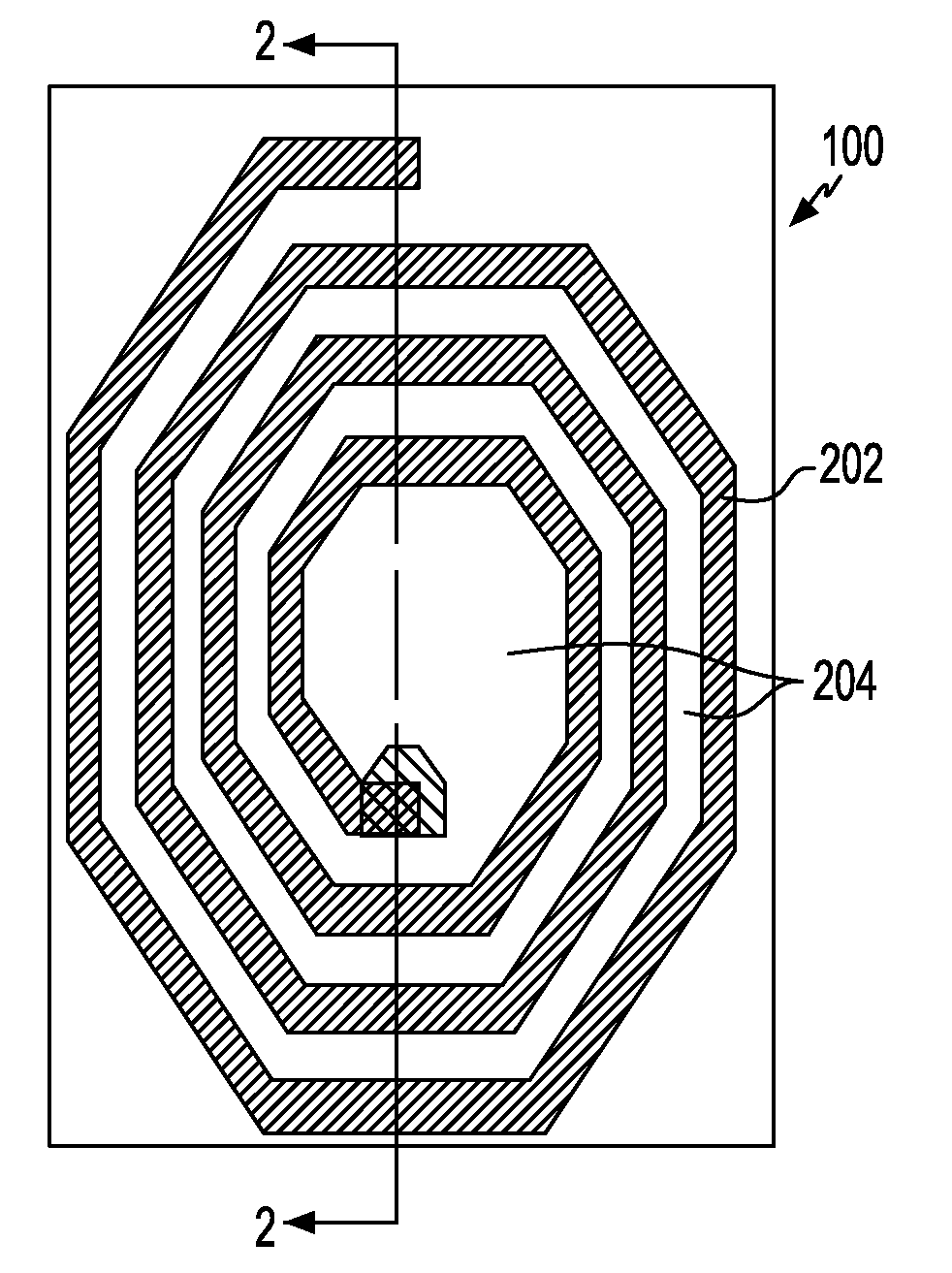
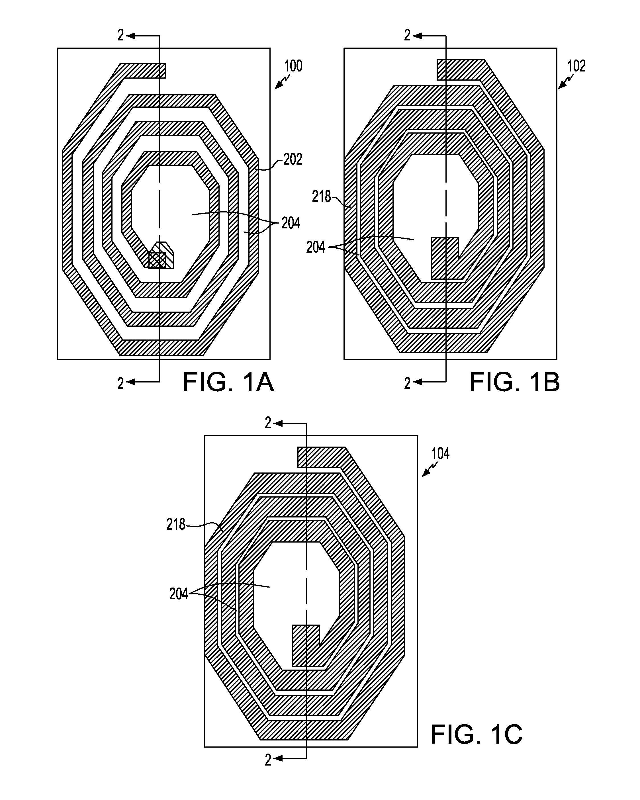
[0024]Referring first to FIGS. 1A, 1B and 1C, there are shown plan views of at least three conductors having spiral turns for use in fabricating an inductor of the exemplary embodiments. Throughout this specification, conductors having spiral turns may also be referred to as spiral conductors and both descriptions are deemed to be equivalent. FIG. 1A illustrates the spiral turns of a top conductor 100, FIG. 1B illustrates the spiral turns of a middle conductor 102 and FIG. 1C illustrates the spiral turns of a bottom conductor 104. There may be more than one bottom conductor layer 104. In use, the top spiral turns of conductor 100 would be placed on top of middle spiral turns of conductor 102 which would then be placed on top of the bottom spiral turns of conductor(s) 104. Dielectric material is formed between the spiral turns of the conductors 100, 102, and 104, between the various conductors 100, 102, and 104 to separate the spiral conductors 100, 102, and 104 and around the variou...


PUM


Abstract

Disclosed is an inductor structure. The inductor structure includes a base material, a plurality of bottom spiral conductors disposed on the base material, and at least one top spiral conductor disposed on the at least one bottom spiral conductor, and dielectric material separating the bottom, middle and top spiral conductors. A current path for high frequency operation is disclosed. Also disclosed is a method for determining the number of turns in the at least one top spiral conductor and the at least one bottom spiral conductor.

Description

RELATED APPLICATION[0001]This application is a continuation in part of U.S. patent application Ser. No. 13 / 012,027, entitled “Inductor Structure Having Increased Inductance Density and Quality Factor”, filed Jan. 24, 2011, the disclosure of which is incorporated by reference herein.BACKGROUND[0002]The present invention relates to the field of inductors, and particularly, to series parallel inductors having a high quality factor and a high inductance density built on a base material such as a semiconductor material.[0003]In the semiconductor industry, digital and analog circuits, including complex microprocessors have been successfully implemented in semiconductor integrated circuits. Such integrated circuits may typically include active devices such as, for example, field effect transistors, and passive devices such as, for example, resistors, capacitors and inductors.[0004]It is desirable to have an inductor with a high quality factor Q and a high inductance density. However, it is...

Claims


Application Information

Patent Timeline
IPC IPC(8): H01F5/00
CPCH01F5/003H01F2017/0086H01F2017/0073H01F17/0013
Inventor GIRARD, PHILIPPE P.D.GROVES, ROBERT A.KONDURU, SRIKUMARVANUKURU, VENKATA N.R.
Owner IBM CORP
Why Eureka
Try Eureka