Contact-less Power Transmitter and Contact-less Power Transmission System

Inactive Publication Date: 2013-05-02
HITACHI CHEM CO LTD
View PDF13 Cites 242 Cited by
  • Summary
  • Abstract
  • Description
  • Claims
  • Application Information

AI Technical Summary

Benefits of technology

[0020]Methods of controlling the power transmission of the transmitting circuit according to the particular charge state of the contact-less power transmitter are outlined below. In one method, the transmission controller calculates the difference between the second period of the load modulation in the transmitting circuit instructed to transmit the power, and the first period of the load modulation in the contact-less power receiver, then if the difference is not smaller than the predetermined reference value, determines that charging of the contact-less power receiver in the storage pocket corresponding to the transmitting circuit has been completed, and stops the power transmission of the transmitting circuit.
[0021]In another method, th

Problems solved by technology

In such a conventional manner of charging 3D glasses, however, repeating AC adapter connection to and disconnection from a connector of the hand-held electronic device has been a troublesome task to the user and has been liable to damage the connector section.
Additionally, differences in electrical standards between hand-held electronic devices have made it necessary to provide a special AC adapter for each hand-held electronic device, and hence posed a problem in that placement of various AC adapters around power outlets renders management of the adapters troublesome.
The technique described in JP-2010-178498-A has had problems in that the charging device needs to have the communications unit for identifying and commun

Method used


Image

  • Contact-less Power Transmitter and Contact-less Power Transmission System
  • Contact-less Power Transmitter and Contact-less Power Transmission System
  • Contact-less Power Transmitter and Contact-less Power Transmission System

Examples


Example

First Embodiment

[0040]A contact-less power transmission system according to a first embodiment of the present invention is described below referring to FIGS. 1 to 12.

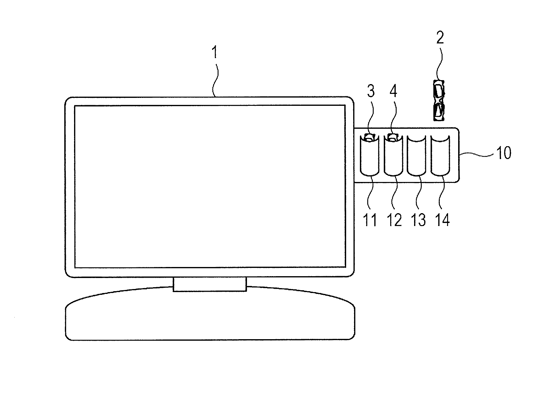
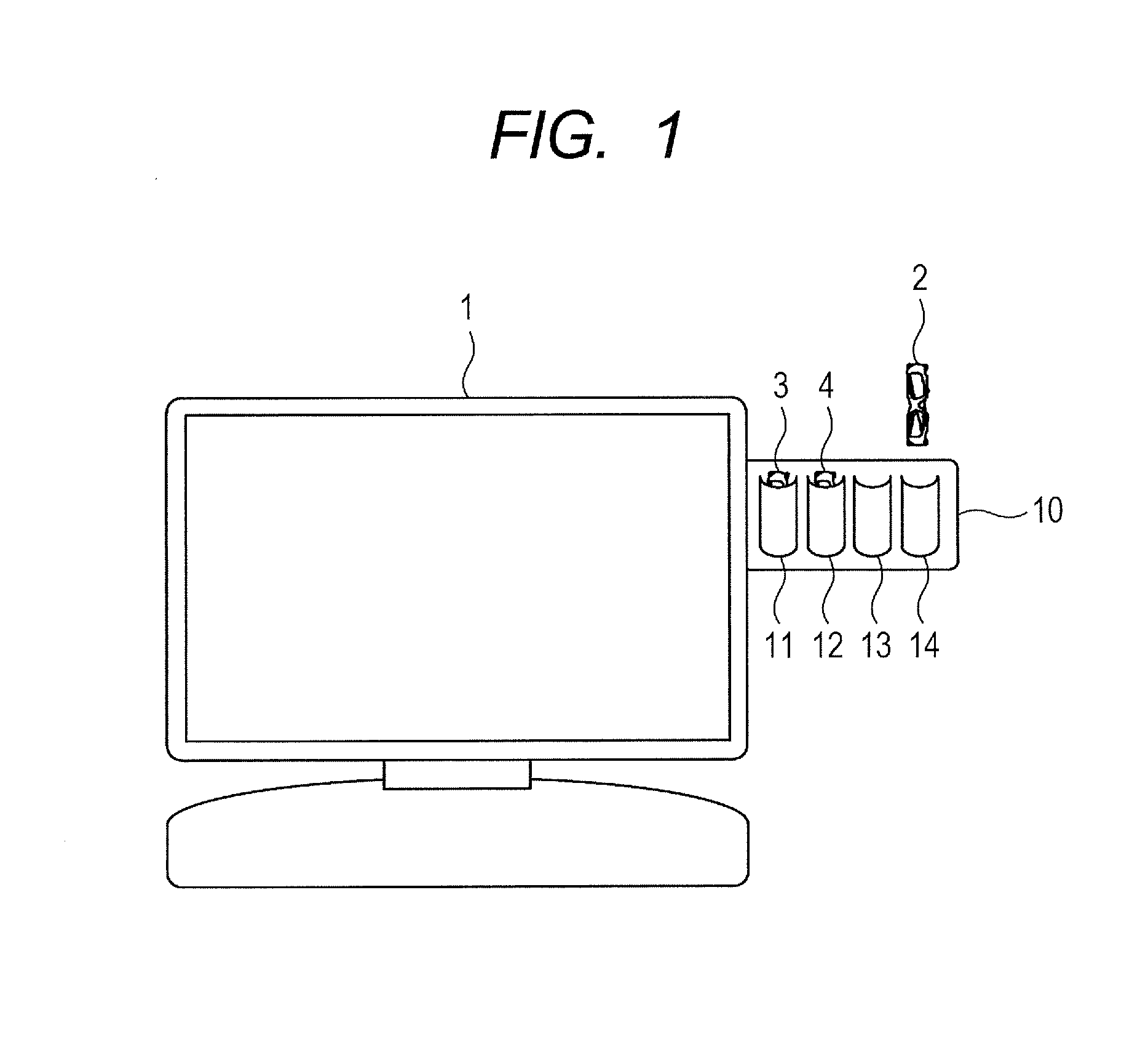
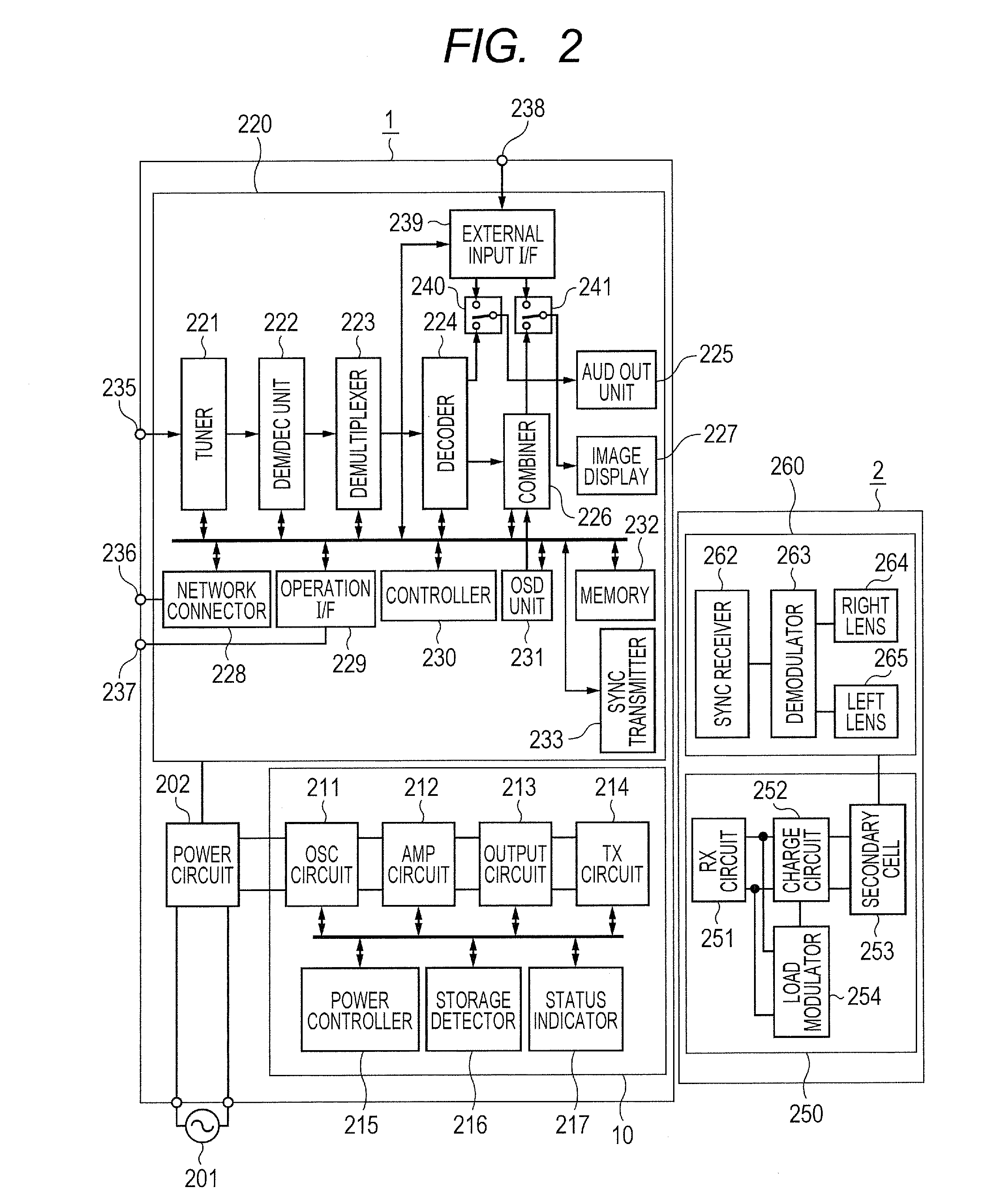
[0041]In the description of the present embodiment, a digital television (DTV) capable of displaying 3D content is taken as an example of a contact-less power transmitter. In addition, a contact-less power transmission system including 3D glasses of an active shutter type that receive a synchronizing signal from the digital TV and open and close liquid-crystal shutters of left and right lenses in synchronization with the TV, is taken as an example of a contact-less power receiver. The present embodiment assumes that a plurality of pairs of 3D glasses exist as contact-less power receivers not subjected to charging.

[0042]First, a configuration of the contact-less power transmission system according to the first embodiment of the present invention is described below referring to FIGS. 1 and 2.

[0043]FIG. 1 is a conceptual d...

Example

Second Embodiment

[0183]Hereunder, a contact-less power transmission system according to a second embodiment of the present invention will be described referring to FIG. 13.

[0184]FIG. 13 is a flowchart showing a charge state determination process conducted in the second embodiment.

[0185]The contact-less power transmission system of the present embodiment is similar to that of the first embodiment in that the system includes a digital TV having a 3D content display capability, as a contact-less power transmitter, and 3D glasses as contact-less power receivers.

[0186]The example in which, in order to determine in step S403 of FIG. 6 whether the object in the storage pocket is the power transmission destination device, the transmission destination device detector 813 is composed using a reflection quantity measuring circuit, and in which the transmission rate sent from the transmission destination device detector 813 as the rate between the amount of incident power and that of reflected ...

Example

Third Embodiment

[0196]Hereunder, a contact-less power transmission system according to a third embodiment of the present invention will be described referring to FIGS. 14 and 15.

[0197]The contact-less power transmission system of the present embodiment is similar to that of the first embodiment in that the system includes a digital TV having a 3D content display capability, as a contact-less power transmitter, and 3D glasses as contact-less power receivers. Means for transmitting electric power in non-contact form is also substantially the same in composition.

[0198]The description of the present third embodiment focuses primarily upon differences from the first embodiment.

[0199]The present embodiment uses an image signal receiving / reproducing block 220 of the digital TV 1 to display a state of power transmission to, and a charge state of, the 3D glasses that are the contact-less power receivers.

[0200]First, a configuration of the contact-less power transmission system according to t...


PUM


Abstract

In a non-contact electric power transmission system that electrically charges a device in a non-contact fashion, a transmitter includes excitation and resonance elements, and transmits power from a specified storage pocket under a control signal from a transmission controller. The transmission controller, upon insertion of an object being detected, uses information from an output detector to determine the object to be a destination device to which power is to be transmitted, and controls the corresponding transmitter circuit to transmit the power. The information from the output detector can include a transmission rate, or a differential between a load modulation period of a receiver and that of the transmitter. The transmission controller acquires charge information on the receiver inserted in one of the storage pockets to control the power transmission. This simplifies the device to be charged for non-contact device charging, and reduces the device in dimensions and weight.

Description

CLAIMS OF PRIORITY[0001]The present application claims priority from Japanese patent application serial no. JP2011-236791, filed on Oct. 28, 2011, the content of which is hereby incorporated by reference into this application.BACKGROUND OF THE INVENTION[0002]The present invention relates generally to contact-less power transmitters and contact-less power transmission systems. More particularly, the invention concerns a contact-less power transmitter and contact-less power transmission system suitable for miniaturizing, as well as electrically charging, electronic devices such as 3D glasses used to view digital TVs.[0003]Nowadays, popular types of portable terminals, cameras, personal computers, and other hand-held electronic devices have a rechargeable battery, which can be repeatedly used if recharged. Through a battery charger, also called an AC adapter, these electronic devices convert home-use alternating-current power into direct-current power and use an internal charging circu...

Claims


Application Information

Patent Timeline
IPC IPC(8): H04N13/04H02J7/04H01F38/14H02J7/00H04N13/332
CPCH04B5/0037H02J7/025H02J5/005H02J7/00302H02J50/12H02J50/40
Inventor TANAKA, MAYUKOSHIROSUGI, TAKATOSHI
Owner HITACHI CHEM CO LTD
Why Eureka
Try Eureka