Method of treatment analysis with particle imaging

a particle imaging and flow cytometer technology, applied in the direction of optical radiation measurement, instruments, spectrometry/spectrophotometry/monochromators, etc., can solve the problems of insufficient use of flow-based imaging systems, and insufficient use of imaging systems for assessing the effectiveness of any effort to deal with such organisms

Active Publication Date: 2013-05-02
YOKOGAWA FLUID IMAGING TECH INC
View PDF1 Cites 16 Cited by
  • Summary
  • Abstract
  • Description
  • Claims
  • Application Information

AI Technical Summary

Benefits of technology

[0012]The method of the present invention enables the evaluation of the effectiveness of a fluid treatment procedure to eliminate particles, such as organisms, from the fluid. When a fluid, such as the water of a watercraft ballast tank, is treated with a cleaning solution, such as chlorine, there is a desire to determine whether sufficient harmful organisms have been destroyed. The method of the present invention allows for that determination by enabling the examination of those organisms before and after the treatment.

Problems solved by technology

The flow-based imaging systems in existence to date have been limited in their usage as an aid to determine the quantity and type of organism contained in a fluid sample.
Beyond that, imaging systems, including flow cytometers, have not been used for the purpose of assessing the effectiveness of any effort carried out to deal with such organisms.
To date, imaging systems have not been used for the purpose of assessing the effectiveness of efforts to neutralize or eliminate organisms of a fluid.

Method used


Image

  • Method of treatment analysis with particle imaging
  • Method of treatment analysis with particle imaging
  • Method of treatment analysis with particle imaging

Examples


Embodiment Construction

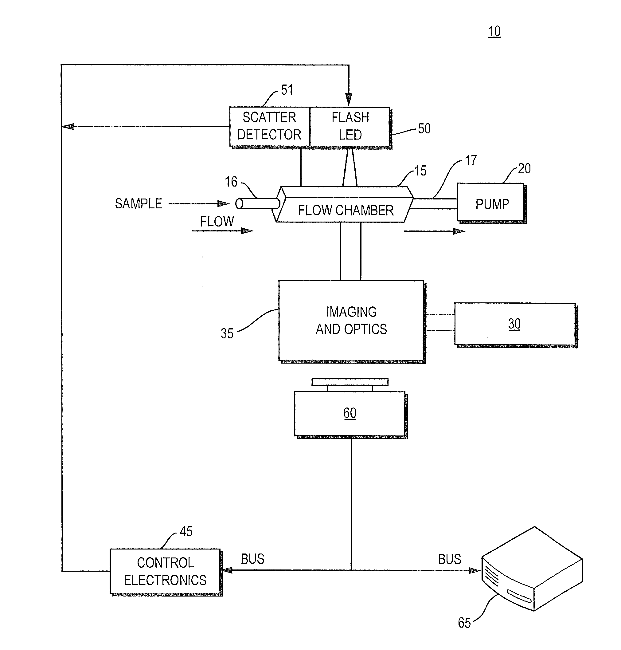
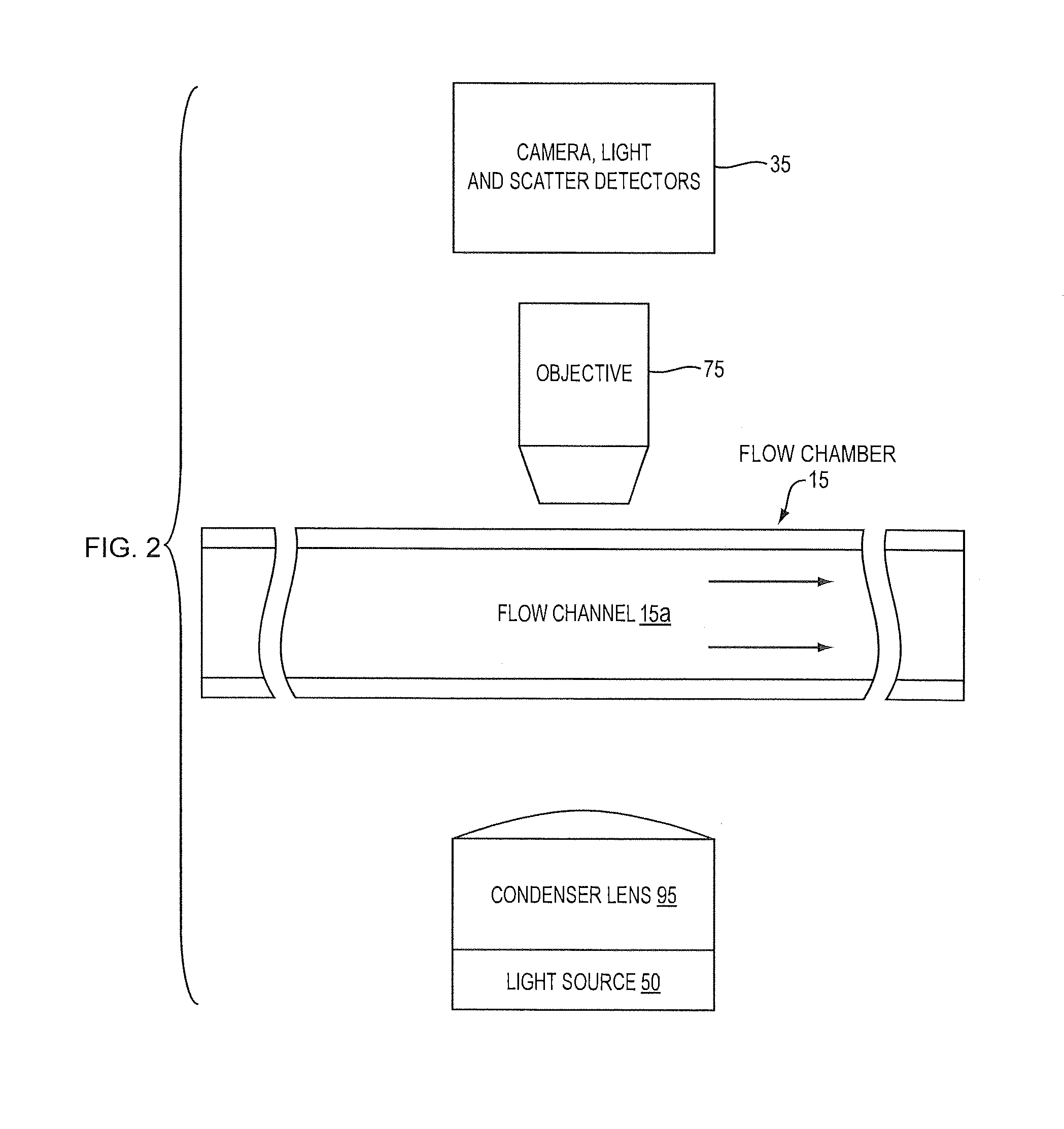
[0020]A system 10 suitable for use in carrying out the method of the present invention in high quality imaging that exist in a fluid sample is shown in FIGS. 1 and 2. The system 10 includes a flow chamber 15, a light source 30, optics 35, an image detection system 40, a backlighting generator 50, an image capturing system 60, a computing device 65, a high NA objective 75 and a high NA condenser lens 95. The combination of these components of the system 10 arranged and configured as described herein enable a user to detect particles in the fluid and produce high resolution images of those particles. The system 10 illustrated is a presentation of one form of the FlowCam® flow-based particle imaging system available from Fluid Imaging Technologies, Inc., of Yarmouth, Me. A flow cytometer may be used for that purpose.

[0021]The flow chamber 15 includes an inlet 20 for receiving the particle-containing fluid to be observed, and an outlet 25 through which the fluid passes out of the flow c...


PUM

PropertyMeasurementUnit
volume/volumeaaaaaaaaaa
particle imagingaaaaaaaaaa
coloraaaaaaaaaa

Abstract

A method for determining the effectiveness of the treatment of a fluid for the purpose of reducing or eliminating particles in the fluid. The method includes the steps of obtaining samples of the fluid before and after treatment, delivering the samples to a particle imaging system, obtaining image information of particles in the samples, including particle colors, and comparing the difference in particle color from the first sample to the second sample. A change in particle color detected is indicative of particle death.

Description

CROSS REFERENCE TO RELATED APPLICATION[0001]The present application is a nonprovisional and claims the priority benefit of pending U.S. provisional patent application Ser. No. 61 / 552,032 filed Oct. 27, 2011, entitled METHOD OF TREATMENT ANALYSIS WITH FLOW CYTOMETER by the same named inventors and held by a common assignee. The entire content of that priority application is incorporated herein by reference.BACKGROUND OF THE INVENTION[0002]1. Field of the Invention[0003]The present invention relates generally to an optical flow imaging and analysis configuration used in particle analysis instrumentation, and more particularly to an optical flow imaging system used to detect the effectiveness of fluid treatment.[0004]2. Description of the Prior Art[0005]The art has seen various optical / flow systems employed for transporting a fluid within an analytical instrument to an imaging and optical analysis area. A liquid sample is typically delivered into the bore of a flow chamber and this sam...

Claims


Application Information

Patent Timeline
Patent Type & Authority Applications(United States)
IPC IPC(8): G01N21/27
CPCG01N21/27G01N2015/1465G01N15/1463G01N2015/1497G01N2015/1493
Inventor DUPLISEA, MATTHEWDRAKE, CORIEIDE, MASON
Owner YOKOGAWA FLUID IMAGING TECH INC
Why Eureka
Try Eureka