Control of a Switch in a Power Converter

a technology of power converter and control switch, which is applied in the direction of efficient power electronics conversion, electric motor control, climate sustainability, etc., can solve the problems of power loss due to charge recovery phenomenon and the loss due to recovered charges, and achieve the effect of a significant part of the total loss of converters of this typ

Active Publication Date: 2013-05-02
STMICROELECTRONICS (TOURS) SAS
View PDF19 Cites 16 Cited by
  • Summary
  • Abstract
  • Description
  • Claims
  • Application Information

AI Technical Summary

Benefits of technology

[0012]An embodiment overcomes all or part of the disadvant

Problems solved by technology

A disadvantage of converters using a chopper switch in hard switching associated with a free wheel diode (PN junction) (for example, in an assembly comprising an inductive element, a chopper switch, and a free wheel diode) is the power loss due to a c

Method used


Image

  • Control of a Switch in a Power Converter
  • Control of a Switch in a Power Converter
  • Control of a Switch in a Power Converter

Examples


Embodiment Construction

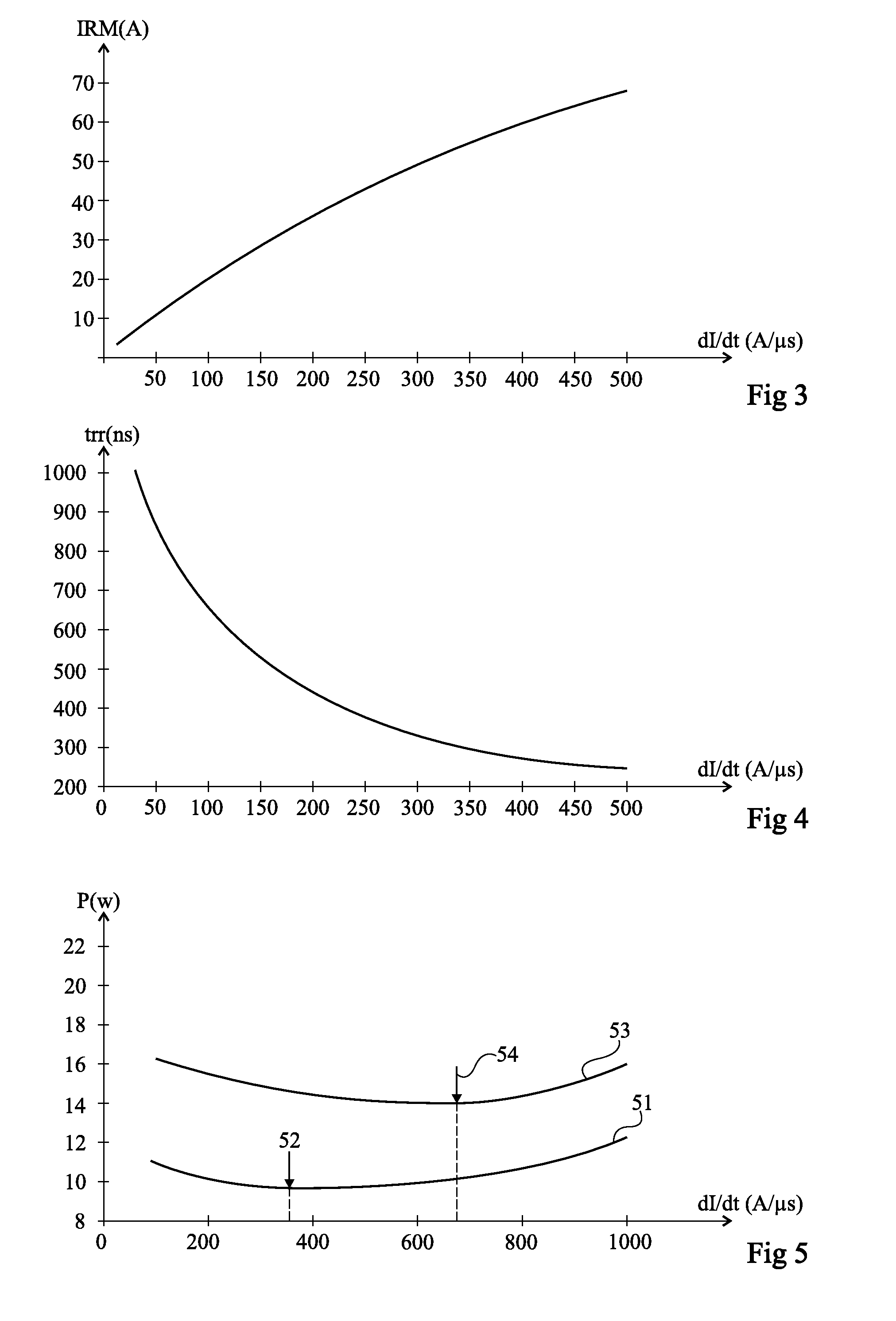
[0036]Studies conducted by the present inventors have shown that the power loss (and accordingly the power efficiency) in a converter using a chopper switch associated with a diode (PN junction) varies according to the current decrease slope in the diode on blocking thereof (or decrease slope of the current in the switch on turning-on thereof). This can be partly explained by the fact that the magnitude of the recovered charge phenomenon in the diode depends on the decrease slope of the current in the diode on blocking thereof. This dependency is illustrated by FIGS. 3 and 4.

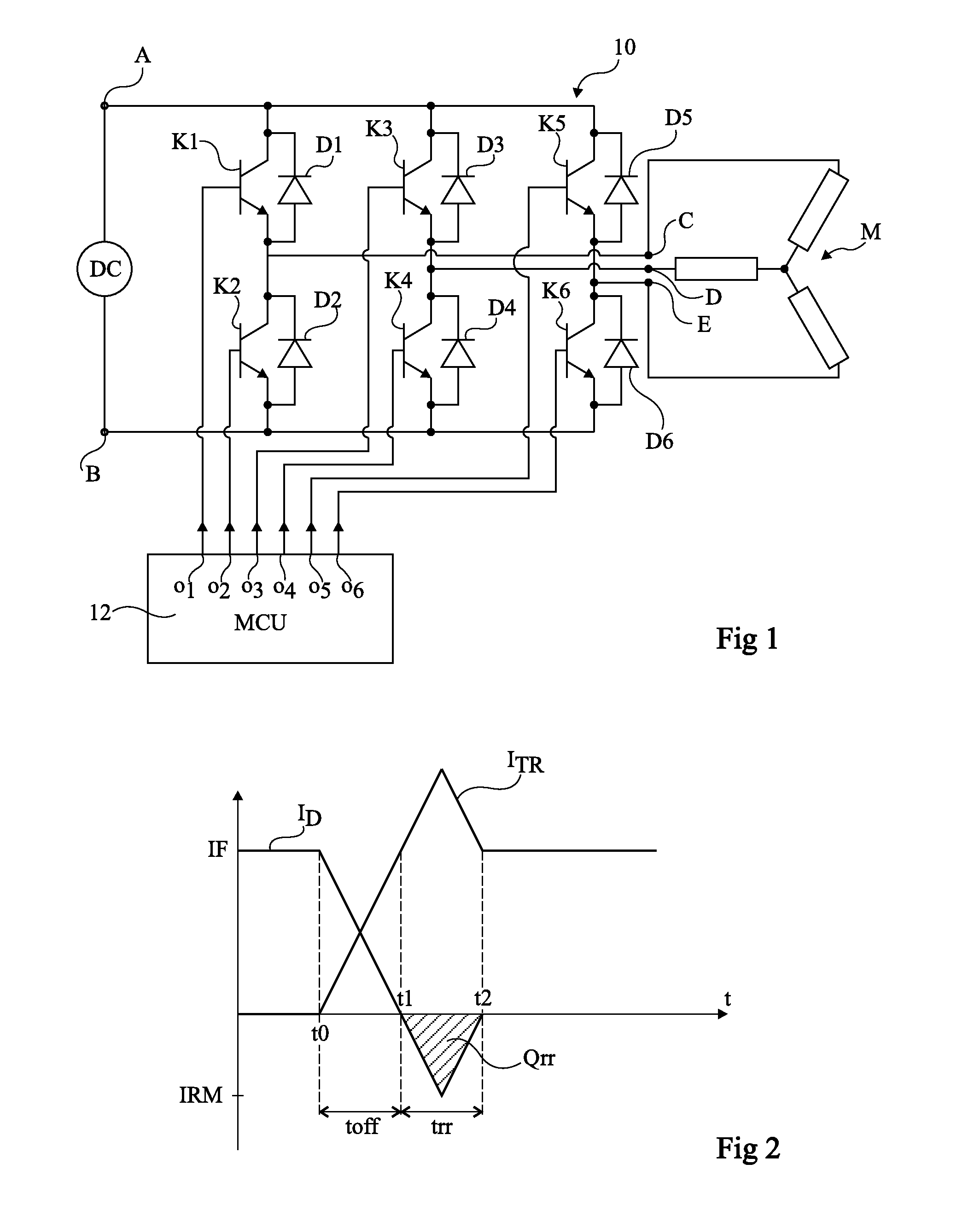
[0037]FIG. 3 is a diagram schematically showing the variation of negative peak voltage IRM (see FIG. 2) of the current in a diode on blocking thereof, according to decrease slope dI / dt of the current. Peak voltage IRM is shown in amperes (A), in absolute value, and current decrease slope dI / dt is shown in amperes per microsecond (A / μs). The diagram of FIG. 3 shows that peak value IRM increases (in absolute value...


PUM


Abstract

A method for controlling at least one switch in a power converter, wherein the switching speed of the switch dynamically varies according to a measurement of a quantity representative of the efficiency of the converter.

Description

CROSS-REFERENCE TO RELATED APPLICATIONS[0001]This application claims the priority benefit of French patent application number 1159751, filed on Oct. 27, 2011, which is hereby incorporated by reference to the maximum extent allowable by law.TECHNICAL FIELD[0002]The present invention generally relates to electronic circuits and, more specifically, to electric signal converters (power converters) using at least one switch switching according to a periodic cycle (chopper switch).BACKGROUND[0003]Many circuits are capable of converting or transforming an electric signal where the regulation of an output signal is ensured by switching one or several switches at a relatively high frequency, for example, greater than 1 kHz. The switches, for example, are transistors (MOS, IGBT, etc.) used in switched mode. By varying the switching frequency and duty cycle, it is possible to control the characteristics of the output signal (shape, frequency, power, voltage, etc.). Circuits of this type compri...

Claims


Application Information

Patent Timeline
IPC IPC(8): H02M7/537
CPCH02P27/085H02P29/0088H02M7/53871H02M1/08H02P2207/01H02P29/68Y02B70/10H02M1/0029H02M1/0054
Inventor GAUTIER, FREDERICRIVET, BERTRAND
Owner STMICROELECTRONICS (TOURS) SAS
Why Eureka
Try Eureka