
Method and Apparatus For Positioning A Vehicle Service Device Relative To A Vehicle Thrust Line

a technology for vehicle service devices and thrust lines, applied in process and machine control, instruments, reradiation, etc., can solve the problems of miscalculation of the distance between, miscalculation of the rate of closure between the two, etc., and achieve the effect of facilitating orientation and placemen

Active Publication Date: 2013-05-02
HUNTER ENG
View PDF27 Cites 70 Cited by
  • Summary
  • Abstract
  • Description
  • Claims
  • Application Information

AI Technical Summary

Benefits of technology

The present disclosure is about a system that helps align a vehicle service apparatus with a vehicle's external sensors. It uses a laser-based alignment device that is mounted on the wheels of the vehicle and an optical target mounted on a machine vision system. The system uses images of the optical targets to guide the alignment of the vehicle's wheels. The system can also communicate with the vehicle's onboard computer to calibrate or align the external sensors. Additionally, the patent describes a method for aligning the front and rear wheels of a vehicle using the laser-based alignment device and mirror reflective targets. The system helps position the vehicle service apparatus or alignment fixture perpendicular to the vehicle's thrust line when aligned. Overall, the system simplifies the process of aligning a vehicle's external sensors, making it easier to perform adjustments.

Problems solved by technology

Any misalignment between the transmission / observation vector and the direction of vehicle travel may result in misidentification of approaching objects, a miscalculation of the distances between the vehicle and the object, and accordingly, a miscalculation of the rate of closure between the two.

Method used


Image

  • Method and Apparatus For Positioning A Vehicle Service Device Relative To A Vehicle Thrust Line
  • Method and Apparatus For Positioning A Vehicle Service Device Relative To A Vehicle Thrust Line
  • Method and Apparatus For Positioning A Vehicle Service Device Relative To A Vehicle Thrust Line

Examples


Embodiment Construction

[0032]The following detailed description illustrates the invention by way of example and not by way of limitation. The description enables one skilled in the art to make and use the present disclosure, and describes several embodiments, adaptations, variations, alternatives, and uses of the present disclosure, including what is presently believed to be the best mode of carrying out the present disclosure.

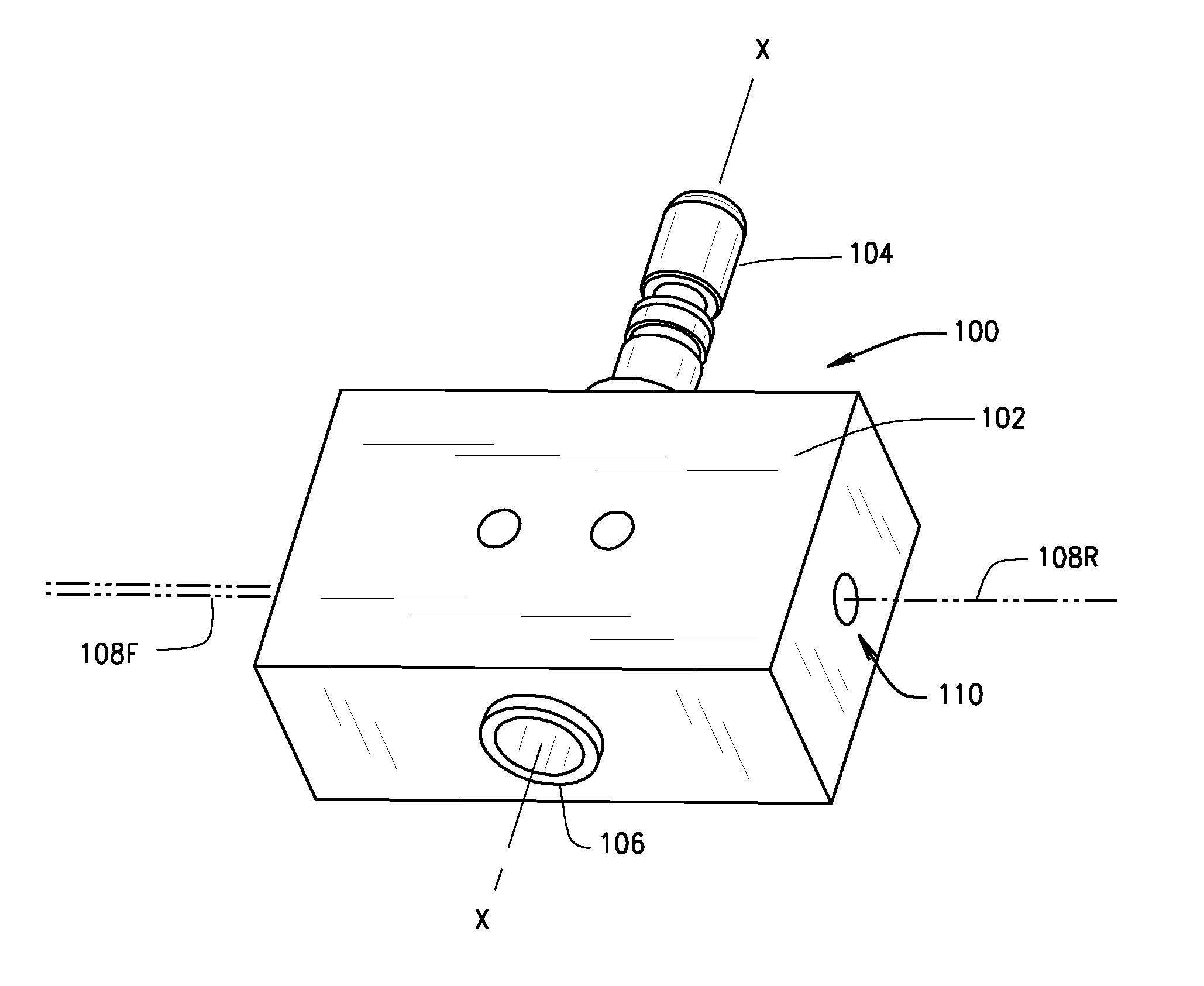
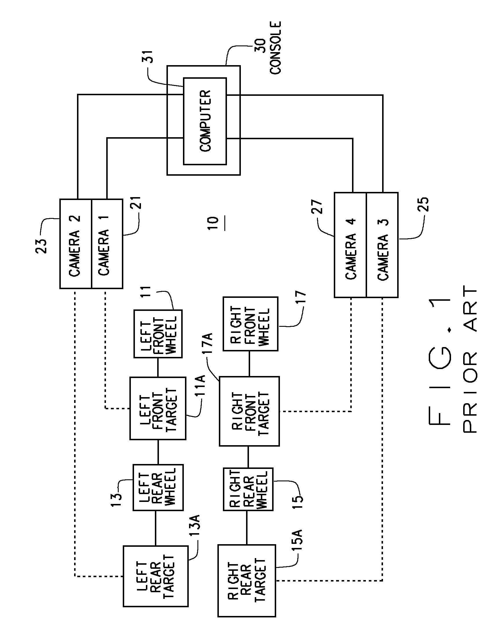
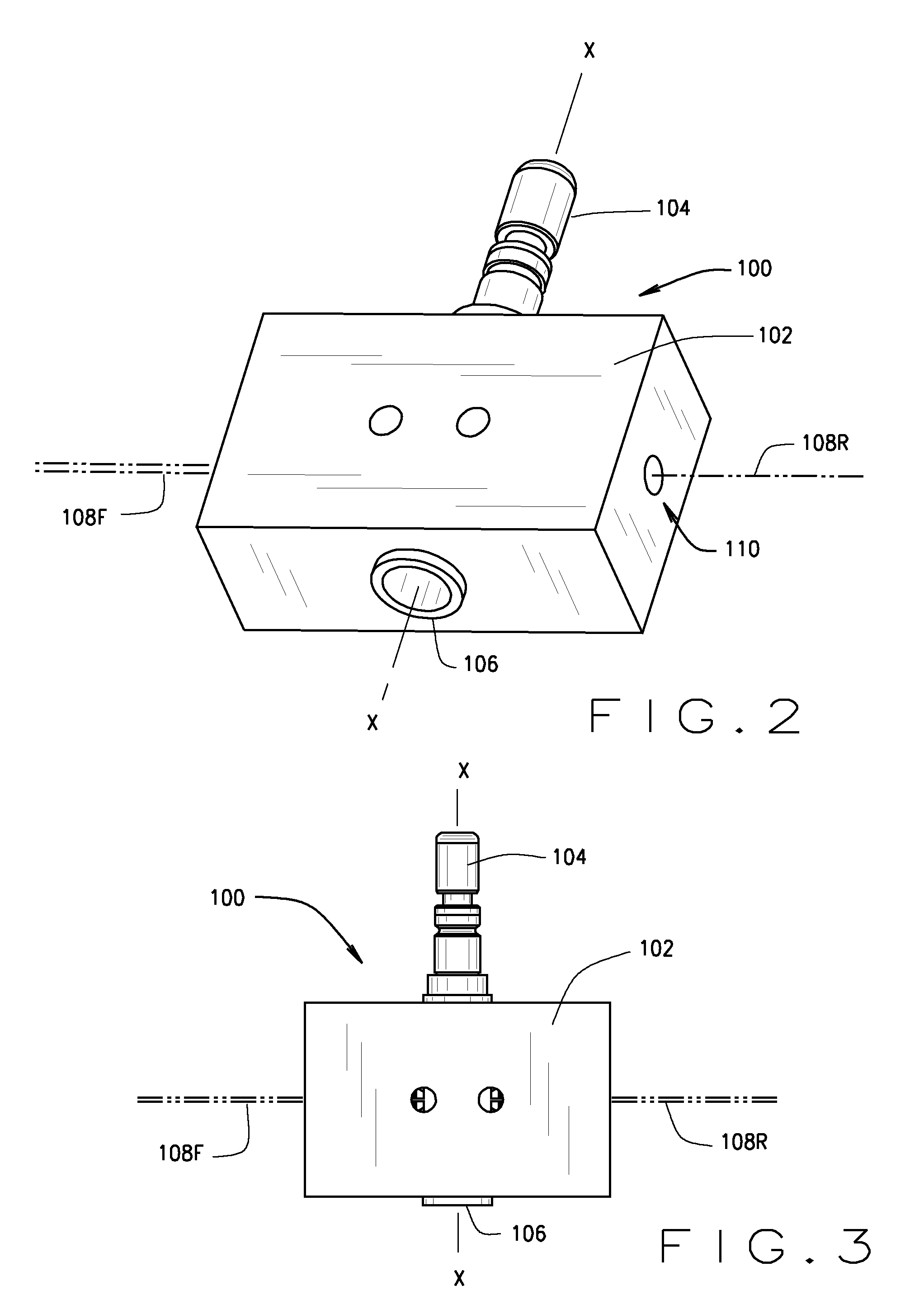
[0033]Turning to FIG. 1, the basic components of a conventional machine vision vehicle wheel alignment system are shown generally at 10. The system 10 is configured to determine the position and orientation of vehicle wheels 11, 13, 15, and 17, and the axis about which they roll. Each vehicle wheel has associated therewith one or more optical targets 11A, 13A, 15A, and 17A. Optionally, additional optical targets may be associated other components of the vehicle, with a lift rack, or other support structure on which the vehicle wheels rest. The images of the optical targets are obtai...


PUM


Abstract

A method and apparatus for utilizing a vehicle wheel alignment system to guide the placement and orientation of a vehicle service apparatus or alignment fixture relative to the thrust line of a vehicle. A laser adapter for projecting a reference line is mounted to a steerable wheel of the vehicle, and is aligned relative to both a line of the vehicle and to the supporting surface on which the vehicle is disposed. The vehicle line is determined by the vehicle wheel alignment system, and the steerable wheel, together with the adapter, are steered relative to the determined vehicle line, such that a projected reference line defined by the position and orientation of the adapter is established parallel to both the supporting surface and the vehicle line. The placement and orientation of the vehicle service apparatus or alignment fixture is subsequently adjusted relative to the projected reference line.

Description

CROSS-REFERENCE TO RELATED APPLICATIONS[0001]The present application is related to, and claims priority from, U.S. Provisional Patent Application Ser. No. 61 / 552,760 filed on Oct. 28, 2011, which is herein incorporated by reference.STATEMENT REGARDING FEDERALLY SPONSORED RESEARCH[0002]Not Applicable.BACKGROUND OF THE INVENTION[0003]The present invention relates to the alignment of vehicle components relative to one or more features of a vehicle, and in particular, to methods and apparatus for utilizing a vehicle wheel alignment system to facilitate adjusting the alignment of sensors associated with forward looking vehicle collision avoidance systems relative to a determined thrust line of the vehicle.[0004]Machine vision vehicle wheel alignment systems have been in use by the vehicle service industry for several years. A typical machine vision vehicle wheel alignment system, such as the Series WA400 wheel alignment system, configured with the Hawkeye Alignment sensors manufactured b...

Claims


Application Information

Patent Timeline
Patent Type & Authority Applications(United States)
IPC IPC(8): G01B11/275G06F17/00
CPCG01B2210/16G01B11/275G01S7/4026G01S13/931G01S2013/93271G01S7/403G01B11/27
Inventor STIEFF, MICHAEL T.
Owner HUNTER ENG
Learn More