Vehicle power source device

Inactive Publication Date: 2013-05-02
PANASONIC CORP
View PDF1 Cites 13 Cited by
  • Summary
  • Abstract
  • Description
  • Claims
  • Application Information

AI Technical Summary

Benefits of technology

[0007]The in-vehicle power supply device is capable of reducing power consumption of the DC/DC converter, with the rec

Problems solved by technology

During the period, electric double-layer capacitor 143 are neither charged nor discharged, the power consum

Method used


Image

  • Vehicle power source device
  • Vehicle power source device
  • Vehicle power source device

Examples


exemplary embodiment 1

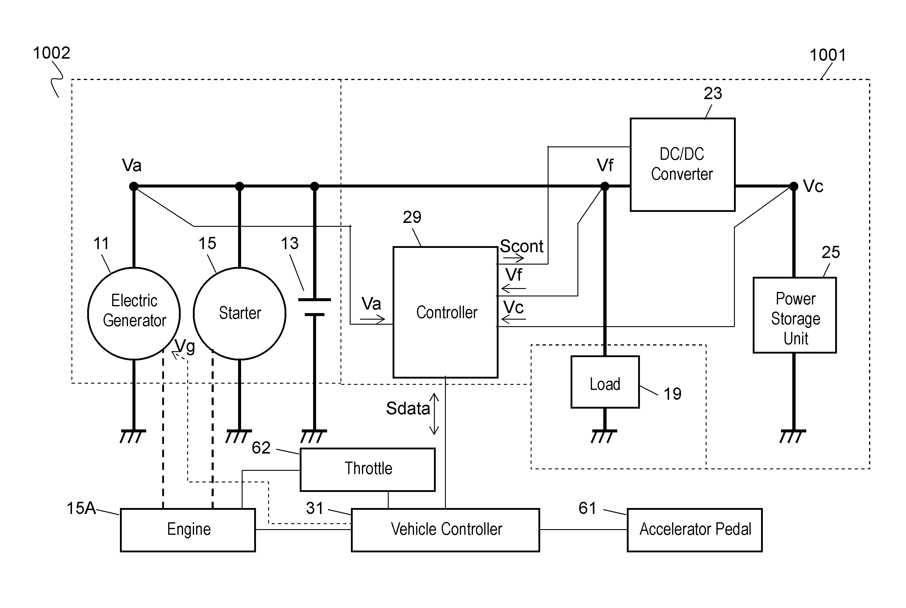
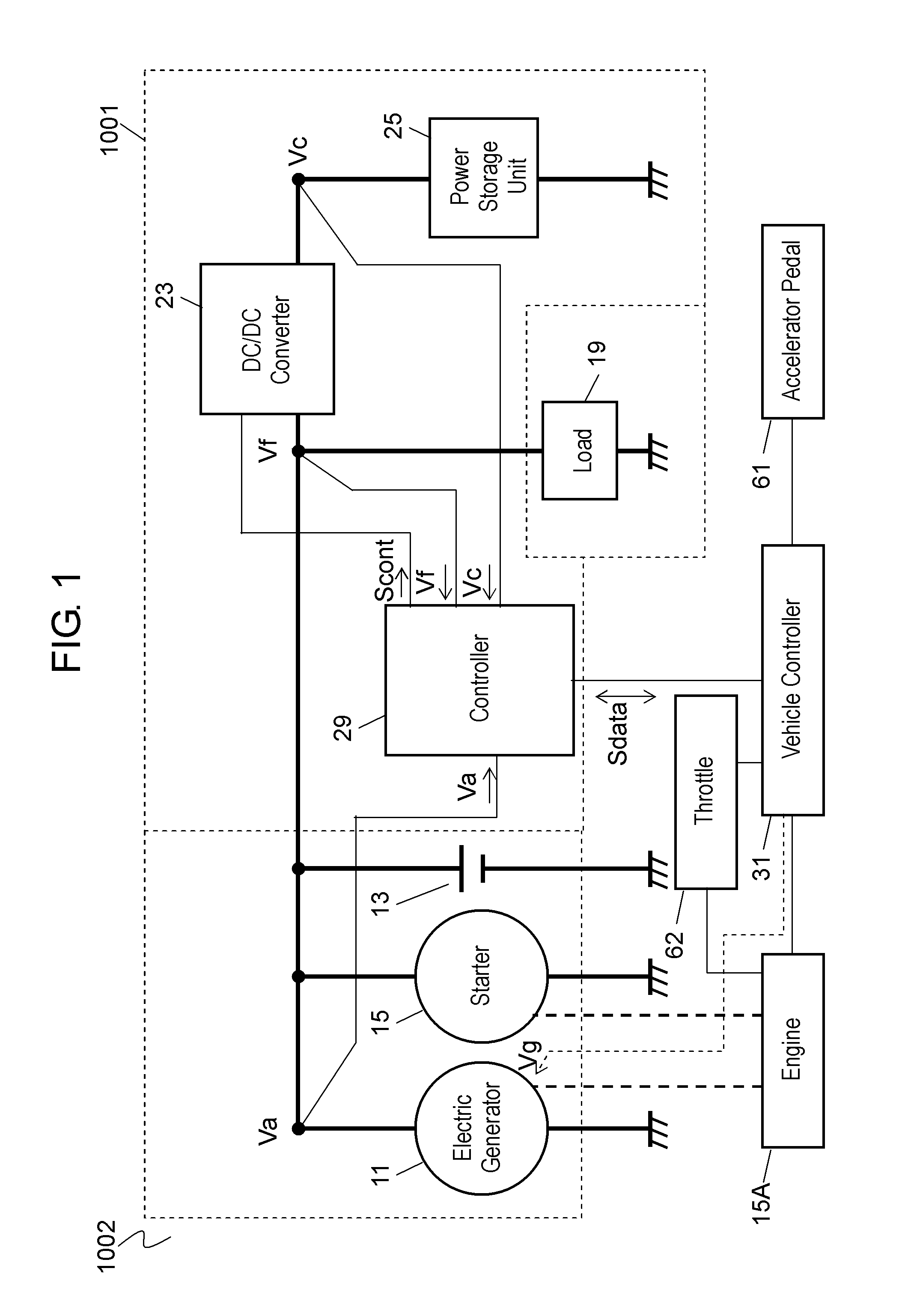
[0017]FIG. 1 is a block circuit diagram of in-vehicle power supply device 1001 for use in a vehicle according to Exemplary Embodiment 1 of the present invention. Vehicle 1002 has engine 15A, electric generator 11, starter 15, main power supply 13, vehicle control circuit 31, load 19, and in-vehicle power supply device 1001 which are mounted to the vehicle.

[0018]Electric generator 11 is electrically coupled with main power supply 13, starter 15, and load 19. Electric generator 11 is driven by engine 15A to generate electric power. The generated electric power includes electric power generated by engine 15A with fuel consumption and regenerative electric power generated by a kinetic energy when vehicle 1002 is in inertial traveling in a fuel-cut state in which fuel supply to engine 15A is halted. In vehicle 1002 according to Embodiment 1, vehicle control circuit 31 controls throttle 62 and engine 15A such that if vehicle speed “v” becomes lower than predetermined speed “vk” even durin...

exemplary embodiment 2

[0096]FIG. 4 is a block circuit diagram of in-vehicle power supply device 1003 for use in a vehicle according to Exemplary Embodiment 2. FIGS. 5A and 5B are flowcharts illustrating operations of in-vehicle power supply device 1003. In FIGS. 4, 5A, and 5B, components having functions identical to those of in-vehicle power supply device 1001 according to Embodiment 1 shown in FIGS. 1, 2A, and 2B are denoted by the same reference numerals. In-vehicle power supply device 1003 according to Embodiment 2 includes controller 89 instead of controller 29 of in-vehicle power supply device 1001 shown in FIG. 1. In in-vehicle power supply device 1003 according to Embodiment 2, controller 89 causes DC / DC converter 23 to operate in the case that charging-status value SOC (storage unit voltage Vc) is larger than lower limit value SOCk (lower limit voltage Vck) and vehicle speed “v” is lower than predetermined speed “vk” when vehicle 1002 decelerates. An operation of in-vehicle power supply device 1...


PUM


Abstract

An in-vehicle power supply device includes an electric generator, a main power supply, a DC/DC converter, a power storage unit connected with the electric generator via the DC/DC converter, and a controller for controlling the DC/DC converter. The DC/DC converter is operable to store, in the power storage unit, regenerative electric power generated by the electric generator, and to discharge the stored regenerative electric power from the power storage unit to the main power supply and the load. The controller is operable to stop the DC/DC converter when a charging-status value indicating a charging status of the power storage unit is not larger than a predetermined lower limit value. The controller is operable to activate the DC/DC converter when the charging-status value is larger than the lower limit value and the vehicle ends deceleration. The controller is operable to activate the DC/DC converter when a speed of the vehicle is not lower than a predetermined speed and an accelerator position of the engine is not larger than a predetermined accelerator position even if the charging-status value is not larger than the predetermined lower limit value. The in-vehicle power supply device is capable of reducing power consumption of the DC/DC converter, with the recovery efficiency of the regenerative electric power being held, thereby resulting in a higher efficiency of the device.

Description

TECHNICAL FIELD[0001]The present invention relates to in-vehicle power supply devices that have a function of recovering their regenerative electric power.BACKGROUND ART[0002]In recent years, vehicles have been developed which have a function of recovering power during deceleration for fuel savings. For such vehicles, a variety of in-vehicle power supply devices for use in vehicles have been proposed. FIG. 7 is a schematic diagram of in-vehicle power supply device 501 disclosed in Patent Literature 1. Engine 131 of the vehicle is mechanically connected to tires 133 and electric generator 135. Electric generator 135 is electrically connected to battery 137 and vehicle electric load 139. Vehicle electric load 139 includes a starter. Electric generator 135 is electrically connected to electric double-layer capacitor 143 via DC / DC converter 141. DC / DC converter 141 is controlled by electronic processor 145.[0003]An operation of in-vehicle power supply device 501 will be described below....

Claims


Application Information

Patent Timeline
IPC IPC(8): B60W20/00B60L11/00
CPCH02J7/1438Y02T10/7275H02J7/16H02J7/345B60L11/00B60W20/00Y10S903/903B60L7/12B60L7/20B60L11/1859B60L11/1862B60L15/2009B60L2210/12B60L2240/12B60L2240/547B60L2240/549B60L2250/26Y02T10/7044Y02T10/7005Y02T10/705Y02T10/7233Y02T10/92H02J7/1446B60L58/13B60L58/14B60L58/15Y02T10/64Y02T10/70Y02T10/72B60W10/08B60W20/13
Inventor AKIMASA, KOJI
Owner PANASONIC CORP
Why Eureka
Try Eureka