Cooling device with a plurality of fin pitches

a cooling device and fin technology, applied in the field of cooling devices, can solve the problems of increasing manufacturing costs, difficult to secure a space, increasing dimensions and weight of cooling devices, etc., and achieve the effects of reducing temperature, reducing manufacturing costs, and suppressing the rise of cooling air temperatur

Inactive Publication Date: 2013-05-09
FURUKAWA ELECTRIC CO LTD
View PDF14 Cites 18 Cited by
  • Summary
  • Abstract
  • Description
  • Claims
  • Application Information

AI Technical Summary

Benefits of technology

[0015]According to the first, the second and the third embodiments of the present invention, a pressure loss of the cooling air due to the windward heat radiation fin group is suppressed, and the amount and velocity of the cooling air passing through the heat radiation fin group on the leeward side can be prevented from being reduced. The cooling capacity on the leeward side is thereby increased so that the cooling capacity can be made uniform across the windward side and the leeward side. Since the cooling capacity can be made uniform, even a large-scale cooling device with a long fin length can without fail provide a cooling capacity across the windward side and the leeward side. In addition, since the number of fins of the windward heat radiation fin group is reduced, it is possible to suppress a temperature rise of the cooling air on the windward side and to supply the cooling air with a lower temperature to the leeward heat radiation fin group. The cooling capacity on the leeward side can be thereby increased. The fin pitch of the windward heat radiation fin group is large, i.e., the number of fins to be installed can be reduced as compared with the conventional example. Therefore, the cooling device can be reduced in size and weight as well as in manufacturing cost. Further, since it is not necessary to install a powerful fan in order to increase the cooling capacity on the leeward side, a space can be saved for installation, and the power consumption for driving the fan can be reduced to decrease environmental loads.
[0016]According to the third embodiment of the present invention, heat pipes are provided. In addition to the aforementioned effects, the cooling capacity is further increased for all the groups from the windward heat radiation fin group to the leeward heat radiation fin group.
[0017]According to the fourth embodiment of the present invention, a pressure loss of the cooling air due to the fins is suppressed. Further, the cooling air flowing between the fins of the respective heat radiation fin groups can be made uniform so that it is possible to efficiently supply cooling air to the respective heat radiation fin groups. In addition, since cooling air can be efficiently supplied to the heat radiation fin groups, the cooling capacity of the leeward heat radiation fin group can be further increased so that the heat-generating element can be cooled without fail even in an enclosed space, e.g., inside the housing of a vehicle.
[0018]According to the fifth embodiment of the present invention, the length of the fins of the windward heat radiation fin group is shorter than the length of the fins of the leeward heat radiation fin group. While the windward heat radiation fin group with a higher cooling capacity can be reduced in size and weight, the cooling capacity of the leeward heat radiation fin group can be increased. Further, by properly adjusting the length of the fins of the windward heat radiation fin group and the leeward heat radiation fin group, the cooling capacity of all the portions of the cooling device can be made as uniform as possible.
[0019]According to the sixth embodiment of the present invention, since the heat pipes are U-shaped or L-shaped in side view, the fins can be mounted effortlessly. The number of fins to be installed and the fin pitch can be properly adjusted, depending on the operation conditions of the cooling device.

Problems solved by technology

However, there is a problem that an increased number of fins 44a results in an increase in the dimensions as well as the weight of the cooling device.
There is a further problem that manufacturing costs are increased.
However, its large size presents the following problems: it is difficult to secure a space for installation; and power consumption for driving the fan is large.

Method used


Image

  • Cooling device with a plurality of fin pitches
  • Cooling device with a plurality of fin pitches
  • Cooling device with a plurality of fin pitches

Examples


first embodiment

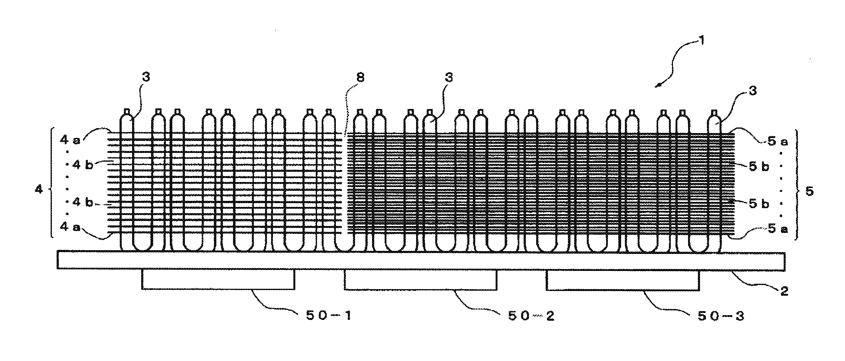
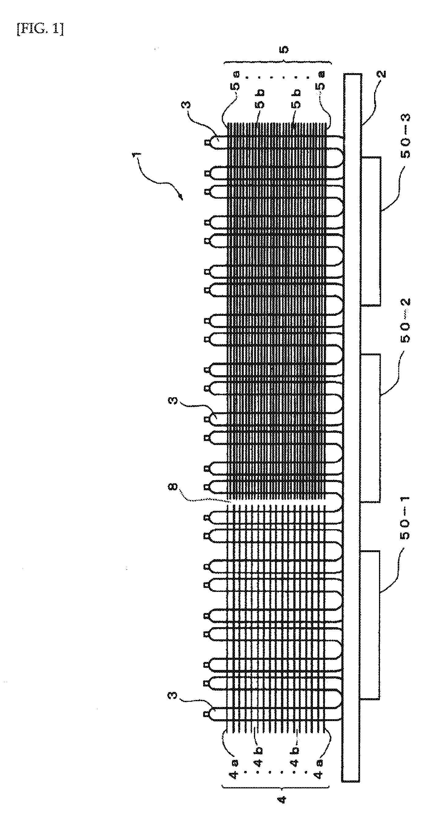
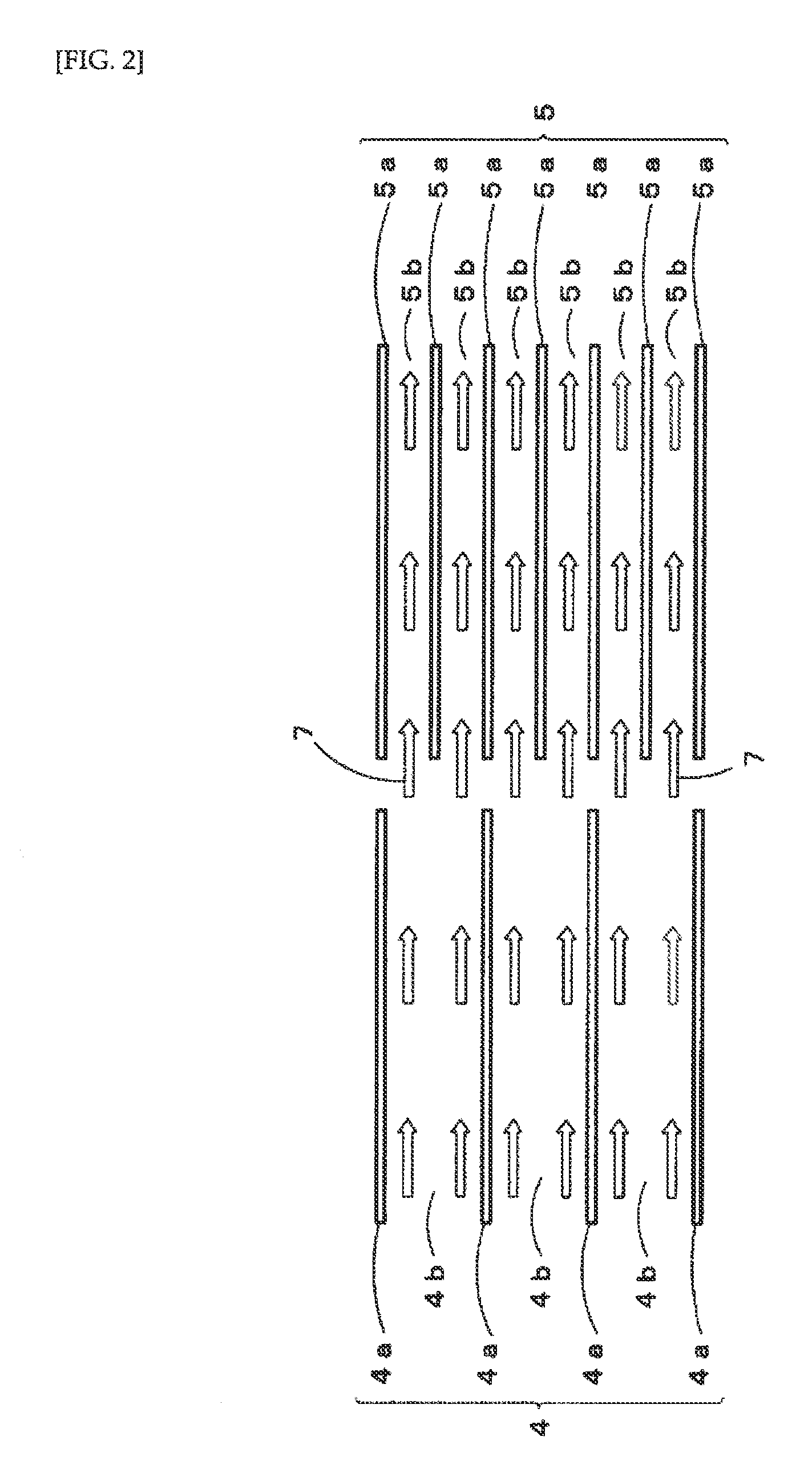
[0039]In the cooling device 1 cooling air is supplied in the direction from left to right in FIG. 1. Further, the cooling device 1 is arranged so that cooling air is supplied in parallel or substantially in parallel with the surface of the heat-receiving block 2, i.e., supplied in parallel or substantially in parallel with the surfaces of each first fin 4a and each second fin 5a. In this way, the cooling air, first, travels through each first fin 4a in the first heat radiation fin group 4. Next, the cooling air having passed through the first heat radiation fin group 4 enters the second heat radiation fin group 5. In turn, the cooling air travels through each second fin 5a in the second heat radiation fin group 5. Therefore, it is possible to prevent the first heat radiation fin group 4 and the second heat radiation fin group 5 from blocking the cooling air. Further, a gap 8 between heat radiation fin groups is formed between the first heat radiation fin group 4 and the second heat...

third embodiment

[0055]The arrangement relationship between the first fins 24a, the second fins 25a and the third fins 26a is not particularly limited as long as the gaps 24b between the first fins 24a are larger than the gaps 25b between the second fins 25a and the gaps 25b between the second fins 25a are larger than the gaps 26b between the third fins 26a. In this embodiment, since the pressure loss due to the first heat radiation fin group 24 can be decreased, a reduction in the amount and velocity of the cooling air passing through the second heat radiation fin group 25 can be suppressed, and the number of first fins 24a is reduced so that a temperature rise of the cooling air having passed through the first heat radiation fin group 24 is suppressed. As the pressure loss due to the second heat radiation fin group 4 can be also decreased, a reduction in the amount and velocity of the cooling air passing through the third heat radiation fin group 26 can be suppressed, and the number of second fins...

second embodiment

[0059]In the cooling device 31 heat-generating elements, which are objects to be cooled, are disposed on the back side of the heat-receiving block 32, on which fins are not mounted. The heat-generating elements are thermally connected to each other and assigned, in the order from windward to leeward, reference numerals 350-1, 350-2, 350-3.

[0060]The arrangement relationship between the first fins 34a, the second fins 35a and the third fins 36a is not particularly limited as long as the gaps 34b between the first fins 34a are larger than the gaps 35b between the second fins 35a and the gaps 35b between the second fins 35a are larger than the gaps 36b between the third fins 36a. In this embodiment, a reduction in the amount and velocity of the cooling air passing through the second heat radiation fin group 35 and the third heat radiation fin group 36 can be suppressed. Also, the numbers of first fins 34 and second fins 35a are reduced so that a temperature rise of the cooling air havi...


PUM


Abstract

It is an object to provide a cooling device with an increased leeward cooling capacity without increasing the number of heat radiation fins to be installed and the amount of cooling air.
The cooling device comprises a heat-receiving block thermally connected to a heat-generating element and heat radiation fin groups having a plurality of fins thermally connected to the heat-receiving block. A flow of cooling air is set in the direction parallel to the heat-receiving block. The plurality of heat radiation fin groups are arranged in tandem along the flow direction of the cooling air. Of the plurality of the heat radiation fin groups, the fin pitch of the heat radiation fin group arranged on the windward side of the cooling air is larger than the fin pitch of the heat radiation fin group arranged on the leeward side of the cooling air.

Description

TECHNICAL FIELD[0001]The present invention relates to a cooling device for cooling a heat-generating element by forced-air cooling, and more particularly to a cooling device that performs forced-air cooling to cool such electronic components as power conversion devices mounted on transportation means including railroad vehicles, aircrafts and ships.BACKGROUND ART[0002]Conventional cooling devices include electronic component cooling devices in housings (hereinafter referred to as the conventional example) shown in FIG. 14. This conventional example comprises a flat plate-shaped heat-receiving block 42; a plurality of heat pipes 43 with a U-shape in side view erected on a surface of the heat-receiving block 42; and a heat radiation fin group 44. The heat radiation fin group 44 has a plurality of fins 44a mounted on the heat pipes 43 in the direction parallel to the heat-receiving block 42, and all the fin pitches between the respective fins 44a are equal (Patent Document 1).[0003]In ...

Claims


Application Information

Patent Timeline
Patent Type & Authority Applications(United States)
IPC IPC(8): F28D1/00
CPCH01L23/427H01L23/467H01L23/3672F28D1/00F28F3/022F28D15/0266H01L2924/0002F28D15/0275F28F1/32F28F2215/04H01L2924/00H05K7/20218H05K7/2039
Inventor FUKAI, HIROYUKIHASHIMOTO, NOBUYUKIYAMADA, HIROSHIIKEDA, MASAMISHIMADA, MAMORU
Owner FURUKAWA ELECTRIC CO LTD
Why Eureka
Try Eureka