Short arc welding system

a technology of short arc welding and short arc welding, which is applied in the direction of arc welding apparatus, welding apparatus, manufacturing tools, etc., can solve the problems of affecting the welding process, and requiring complex and expensive welding apparatuses. , to achieve the effect of preventing drift of reference current, good control of current ramp shape, and high accuracy

a technology of short arc welding and short arc welding, which is applied in the direction of arc welding apparatus, welding apparatus, manufacturing tools, etc., can solve the problems of affecting the welding process, and requiring complex and expensive welding apparatuses. , to achieve the effect of preventing drift of reference current, good control of current ramp shape, and high accuracy

US20130112674A1Active Publication Date: 2013-05-09ESAB AB

Image

  • Short arc welding system
  • Short arc welding system
  • Short arc welding system

Examples


Embodiment Construction

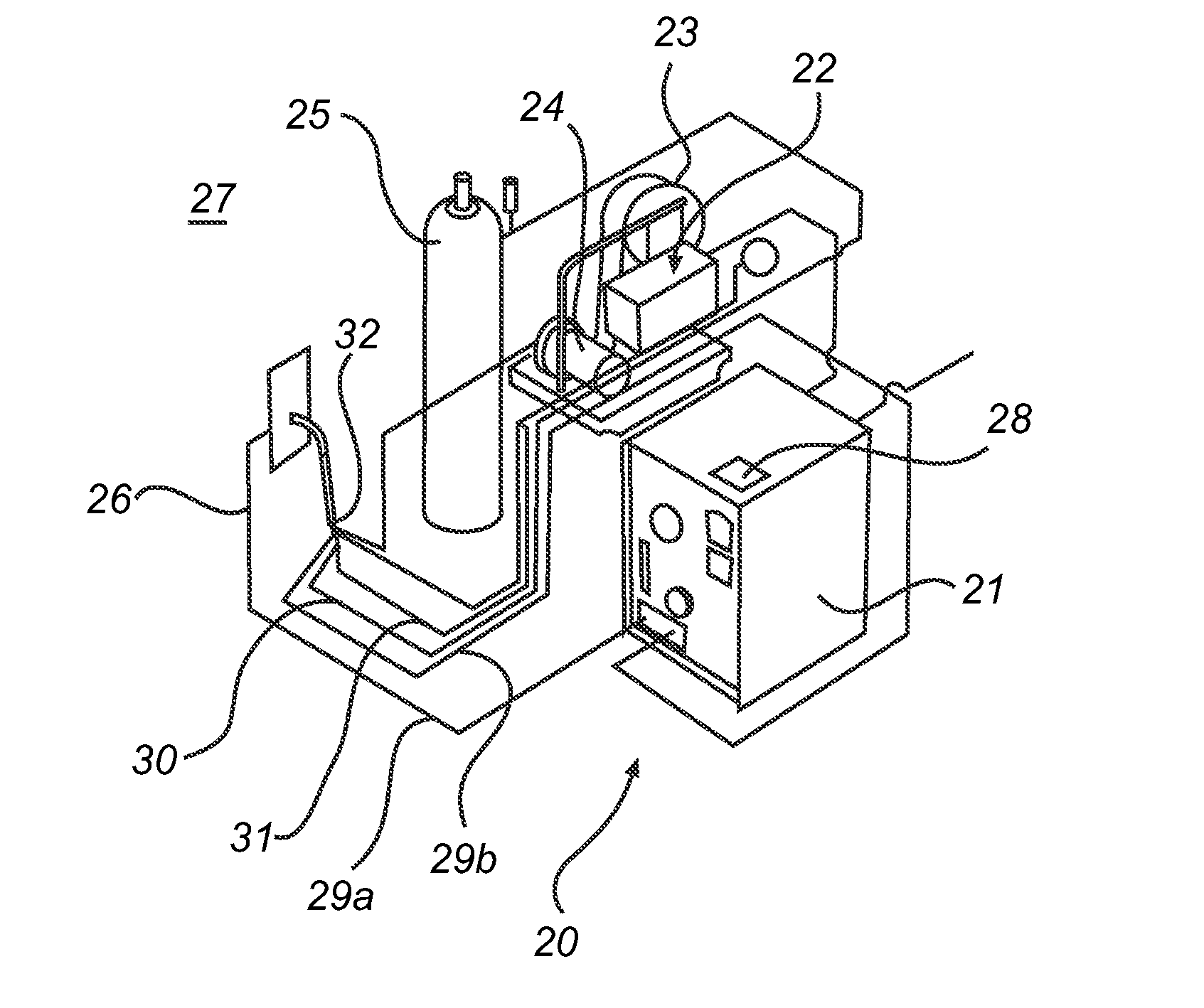
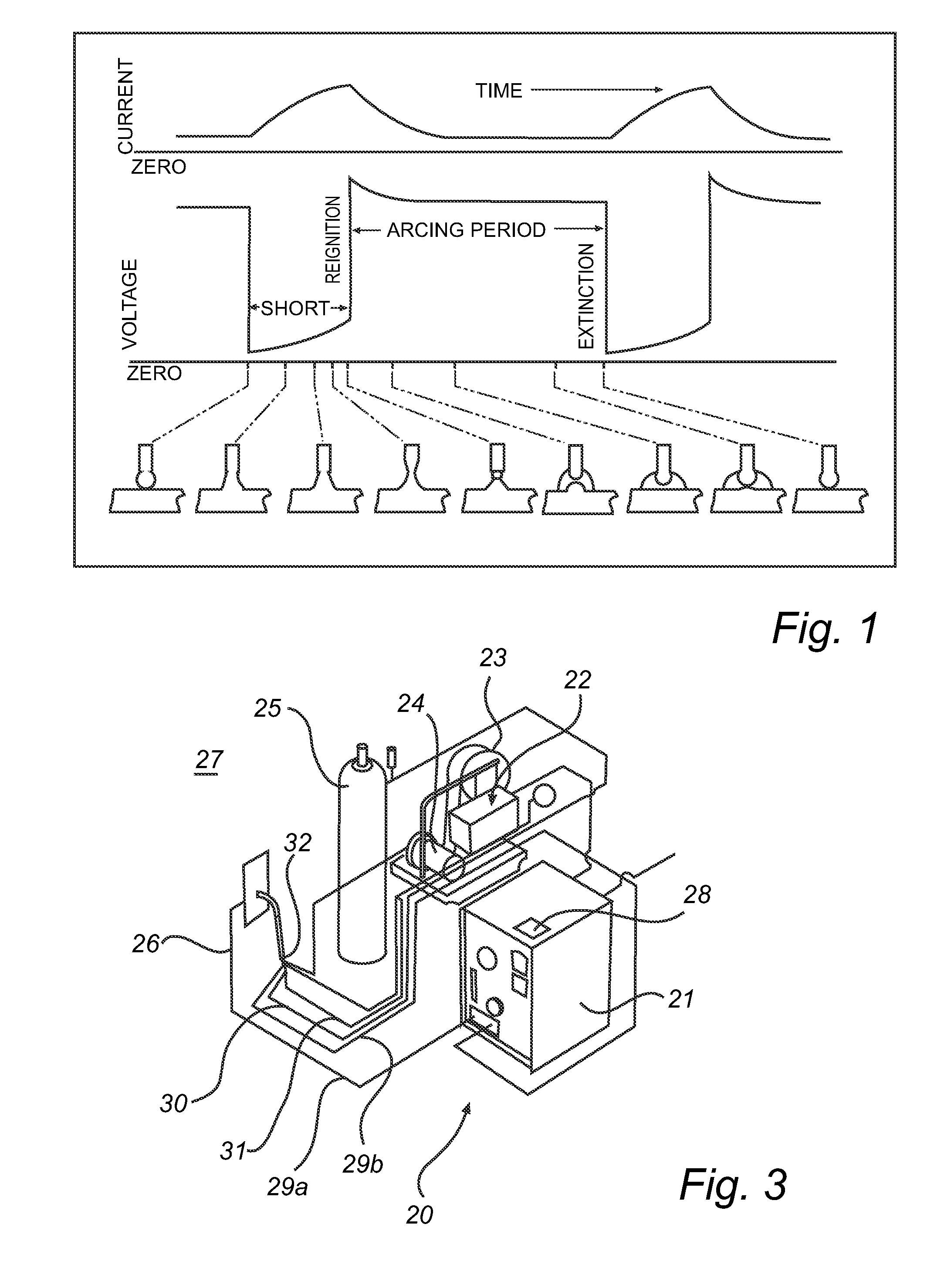
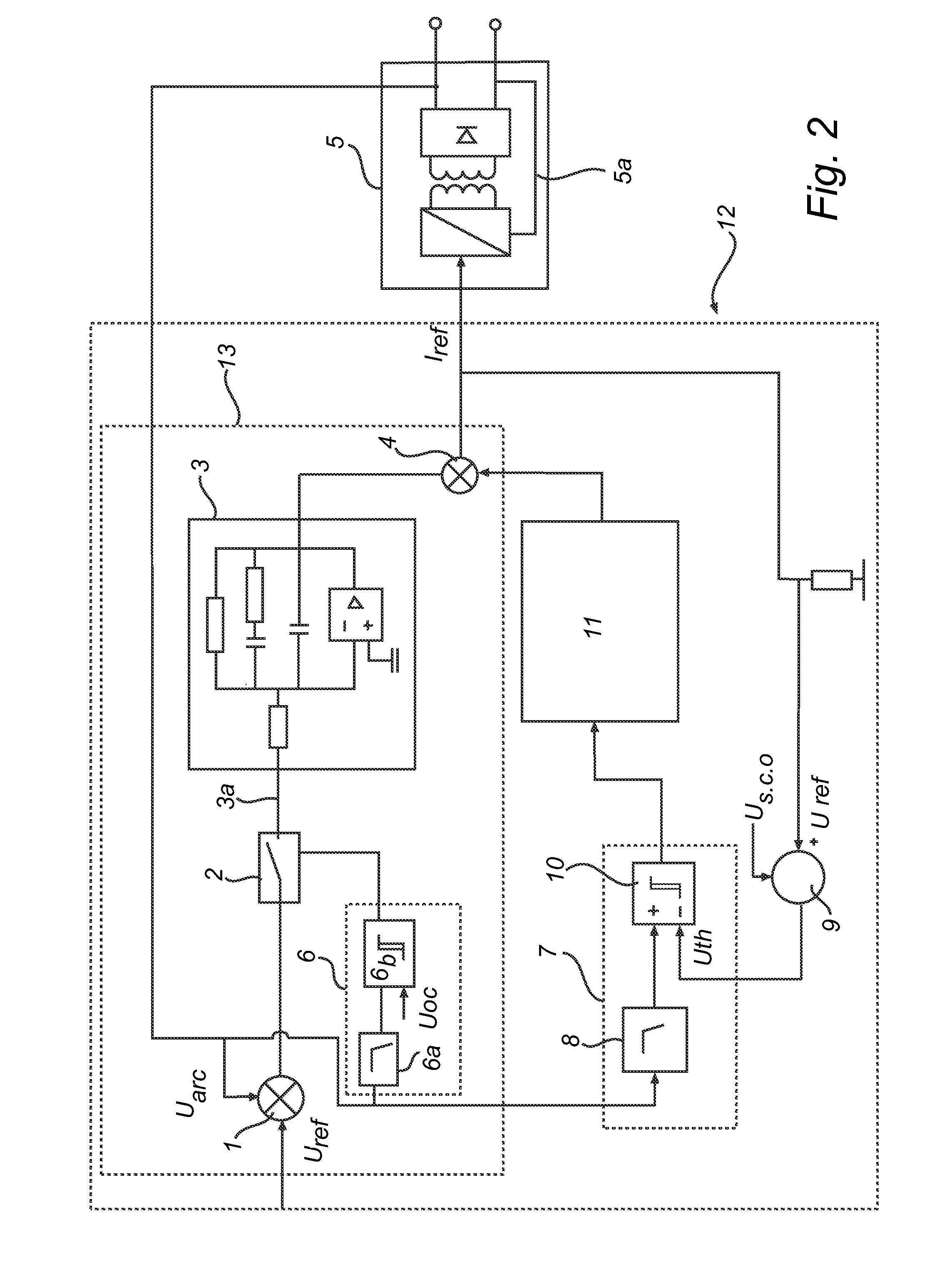
[0048]FIG. 2 shows a system 12 for controlling a weld-current in an arc welding apparatus 20 (FIG. 3) for short arc welding.

[0049]A voltage feedback loop 13 controls the voltage at a welding electrode connected to a constant current power source.

[0050]The constant current power source includes a current feedback loop 5a which compares an output current with a reference current provided from a system 12 for controlling a weld-current in the arc welding apparatus 20 (FIG. 3). A current regulator included in the constant current power supply 5 controls the output current of the power supply in dependence of a regulation error between the reference current and the output current.

[0051]The voltage feedback loop 13 includes a subtraction node 1 where the output voltage Uarc is subtracted from the reference voltage Uref in the node 1. The difference between the output voltage Uarc and the reference voltage Uref constitutes a regulation error E, which is delivered to the PI regulator 3 as a...


PUM

PropertyMeasurementUnit
voltagesaaaaaaaaaa
weld-current aaaaaaaaaa
thresholdaaaaaaaaaa

Abstract

A system for controlling a weld-current in an arc welding apparatus for short arc welding comprising a current regulator included in a voltage feedback loop from a power supply to a welding electrode and a ramp generator arranged to provide current ramps during a short circuit phase at said welding electrode.

Description

FIELD OF INVENTION[0001]The present invention relates to a system for controlling a weld-current in a direct current arc welding apparatus for short arc welding. The present invention in particular relates to a system for controlling a weld-current in an direct current arc welding apparatus for short arc welding comprising a current regulator included in a voltage feedback loop, and a ramp generator arranged to provide current ramps during a short circuit. The invention furthermore relates to a method for controlling a power source.BACKGROUND OF INVENTION[0002]The present invention relates to a system for controlling a weld-current in a direct current arc welding apparatus for short arc welding. Short arc welding is a metal transfer mode in gas metal arc welding where a drop of molten metal will dip into a weld pool before detachment from a consumable electrode in a process of metal transfer.[0003]In gas metal arc welding a consumable electrode is continuously fed towards a welding ...

Claims


Application Information

Patent Timeline
09 May 2013
Publication
US20130112674A1
IPC
B23K9/10
CPC
B23K9/073; B23K9/1006; B23K9/095; B23K9/091; B23K9/09; B23K9/10
Inventors
MNICH, ANDRZEJ