Rotor and ipm motor

a technology of rotor and motor, which is applied in the direction of dynamo-electric machines, magnetic circuit rotating parts, and shape/form/construction of magnetic circuits, etc. it can solve the problem of low estimate of commercially developed deposits, ineffective reduction and difficulty in reducing the usage amount of dysprosium or the like used to secure a coercive force against this demagnetizing field. the effect of coercive force and reduced

Active Publication Date: 2013-05-09
TOYOTA JIDOSHA KK
View PDF11 Cites 15 Cited by
  • Summary
  • Abstract
  • Description
  • Claims
  • Application Information

AI Technical Summary

Benefits of technology

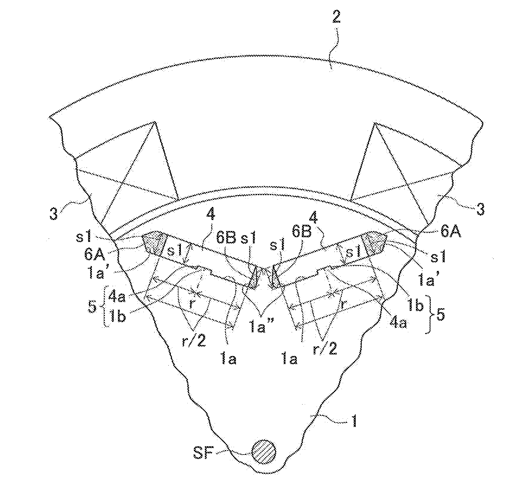
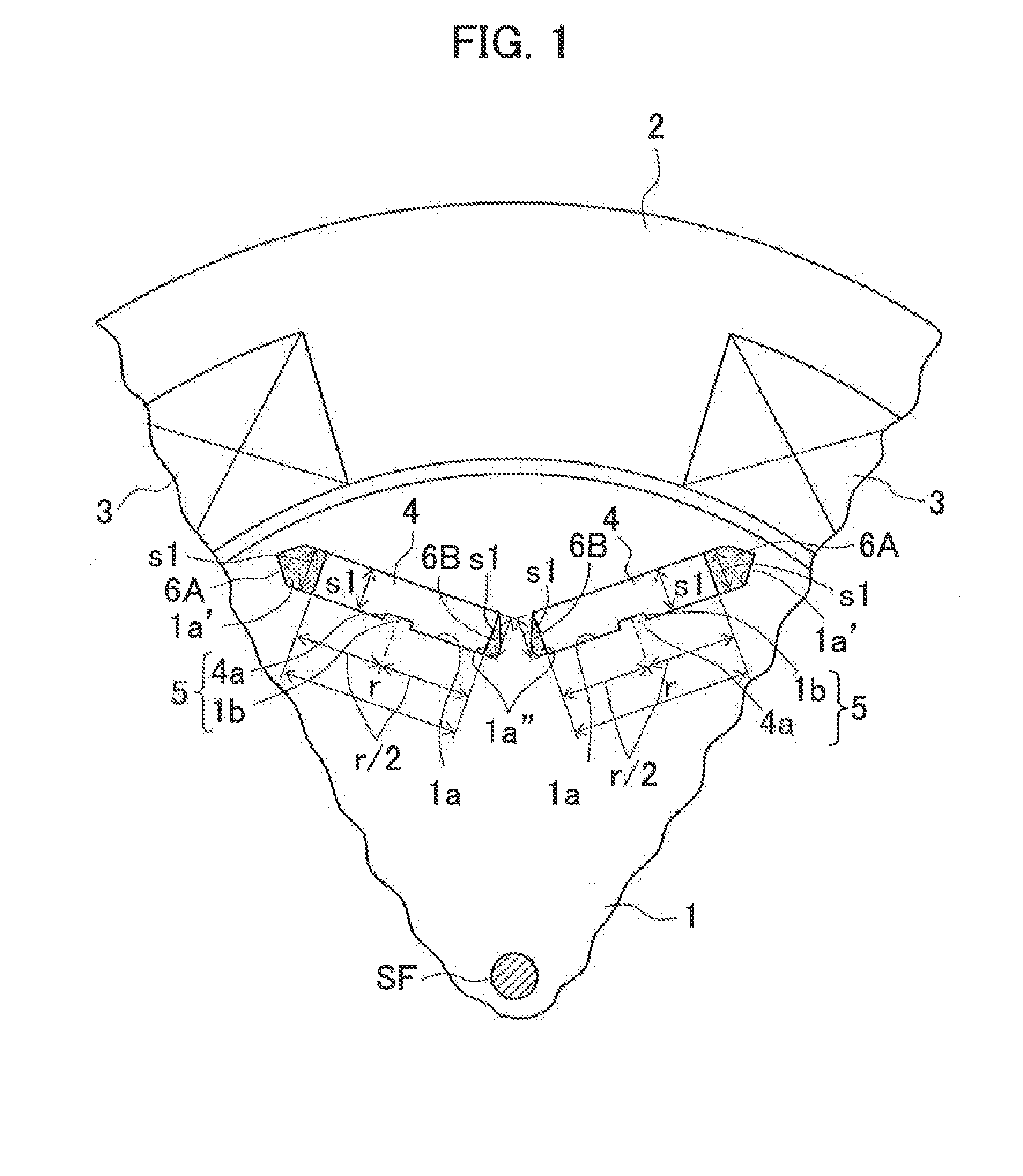
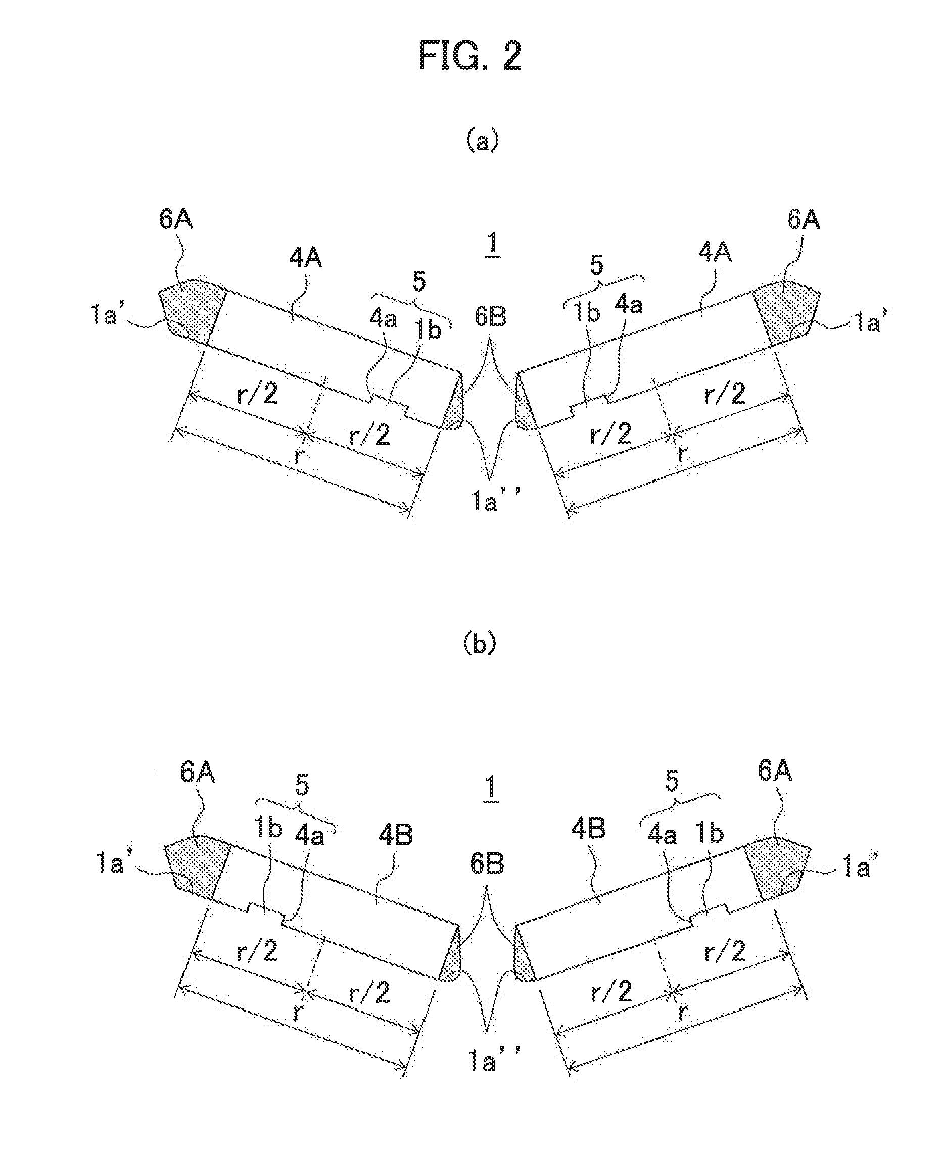
[0039]As is understood from the above description, according to a rotor of the present invention and an IPM motor provided with the rotor, a slot bored in the rotor and a magnet to be inserted therein are aligned and fixed via an engagement part including a concave groove and a protrusion formed at their corresponding positions, and a flux barrier formed between a lateral side face of the ma

Problems solved by technology

However, the usage amount of dysprosium or terbium greatly exceeds the natural abundance ratio of rare-earth elements and additionally the estimated amount of commercially developed deposits is extremely low, and moreover the existing regions of the deposits are eccentrically located across the world, and therefore the necessity of strategy for these elements has been recognized.
Even if a coercive-force distribution magnet is manufactured including dysprosium or the like with the impregnation amount corresponding to a required coercive fo

Method used


Image

  • Rotor and ipm motor
  • Rotor and ipm motor
  • Rotor and ipm motor

Examples


Embodiment Construction

model of a magnet and a slot and FIG. 5(b) is a contour figure of demagnetizing field obtained by magnetic analysis thereof.

[0045]FIG. 6 shows a result of magnetic analysis to find demagnetizing field in a magnet, where FIG. 6(a) shows Example 2 model of a magnet and a slot and FIG. 6(b) is a contour figure of demagnetizing field obtained by magnetic analysis thereof.

[0046]FIG. 7 shows a result of magnetic analysis to find demagnetizing field in a magnet, where FIG. 7(a) shows Example 3 model of a magnet and a slot and FIG. 7(b) is a contour figure of demagnetizing field obtained by magnetic analysis thereof.

[0047]FIG. 8(a) is a schematic view partially showing a rotor and a stator making up a conventional IPM motor, and FIG. 8(b) is an enlarged view of part b of FIG. 8(a) describing the state where flux from a stator concentrates on a corner area of the magnet on the stator side.

MODE FOR CARRYING OUT THE INVENTION

[0048]The following describes embodiments of the present invention, w...


PUM


Abstract

Disclosed are a rotor and an IPM motor capable of avoiding concentration of flux on a corner area of a magnet on the stator side, leading to reduction in demagnetizing field and accordingly reduction in a required coercive force, and reduction in the usage amount of dysprosium or the like and accordingly reduction in manufacturing cost. In a slot bored in a rotor core of a rotor making up a motor, at at least one of a slot face on a center side of the rotor core and a slot face facing this slot face is formed a protrusion or a concave groove, and the magnet to be inserted in the slot includes at least one of a concave groove and a protrusion to be engaged with the protrusion or the concave groove of the slot face at a position corresponding to the protrusion or the concave groove formed in the slot. Then, these concave groove and protrusion are engaged to form an engagement part. This engagement part aligns and fixes the magnet in the rotor, and a flux barrier is formed between a lateral side face of the magnet and a slot face, the flux harrier having a same thickness as a thickness of the magnet.

Description

TECHNICAL FIELD[0001]The present invention relates to a rotor making up a motor and an IPM rotor provided with this rotor.BACKGROUND ART[0002]An interior permanent magnet motor (hereinafter called an IPM motor) including a permanent magnet embedded inside a rotor can generate reluctance torque as well as magnet torque resulting from attractive force / repulsive force between a coil and the permanent magnet, and therefore compared with a surface permanent magnet motor (SPM motor) including a permanent magnet attached to an outer periphery of a rotor, the IPM motor has higher torque and higher efficiency. Therefore such an IPM motor is used as driving motors in hybrid vehicles, electric vehicles and the like requiring high output performance. Typically used permanent magnets therefore include sintered magnets of rare-earth magnets, ferrite magnets, alnico magnets and the like.[0003]In order to realize smooth insertion of a permanent magnet into a slot formed in a rotor core and to avoid...

Claims


Application Information

Patent Timeline
IPC IPC(8): H02K1/27
CPCH02K1/2766H02K1/274H02K2213/03
Inventor KOGURE, TOMONARIKURIHARA, HIROKO
Owner TOYOTA JIDOSHA KK
Why Eureka
Try Eureka