Surface Light Guide and Planar Emitter

a technology of surface light guide and planar emitter, which is applied in the direction of planar/plate-like light guide, lighting and heating apparatus, instruments, etc., and can solve problems such as the distribution of ligh

Inactive Publication Date: 2013-05-09
OSRAM OPTO SEMICONDUCTORS GMBH & CO OHG
View PDF1 Cites 34 Cited by
  • Summary
  • Abstract
  • Description
  • Claims
  • Application Information

AI Technical Summary

Benefits of technology

[0014]By means of the light guiding regions of different types, the surface light guide can be formed such that the scattering effect in the light guide can be adapted for the respective radiation components. In particular, the first layer and the second layer can be formed so as to compensate for a wavelength-dependent scattering effect at the individual scattering locations. In contrast thereto, a conventional surface light guide comprises a single light guiding region, in which all radiation components propagate, such that a wavelength-dependent scattering effect of the scattering locations has the effect that the wavelength components for which the scattering effect is highest emerge from the surface light guide with an increased probability.
[0026]In accordance with at least one embodiment, the surface light guide is provided for coupling in radiation having a first radiation component and a second radiation component, wherein the radiation components differ from each other with regard to a peak wavelength. The first layer and the second layer are decoupled from each other with regard to the light guidance. The first layer and the second layer are each adapted to a respective radiation component with regard to the scattering effect, such that they compensate for a wavelength dependence of the scattering effect.
[0040]In a first variant, the material of the first layer has an anomalous dispersion. Anomalous dispersion has the effect, for example, that the refractive index is higher in the red spectral range than in the blue spectral range. On account of the different angle for total reflection, the first layer acts as a light guide for a greater proportion of the radiation in the red spectral range than for the radiation in the blue spectral range. The first layer preferably has a higher concentration of scattering locations than the second layer and the further layer. The second and / or the further layer can also be formed more extensively in a manner free of scattering locations.
[0041]In a second variant, the material of the first layer has a normal dispersion. In this case, predominantly the radiation having the shorter wavelength, for example blue radiation, propagates in the first layer. For efficiently coupling out the radiation having the longer wavelength, the scattering locations are arranged preferably exclusively or at least with a higher concentration in the second layer and / or the third layer.
[0045]A structure size of the structuring is furthermore preferably smaller than the resolving power of the human eye. What is thus achieved is that the surface light guide, despite the structuring, appears to the eye as a homogeneous, unstructured area.

Problems solved by technology

However, this can result in a luminance distribution that is comparatively inhomogeneous over the radiation exit area.

Method used


Image

  • Surface Light Guide and Planar Emitter
  • Surface Light Guide and Planar Emitter
  • Surface Light Guide and Planar Emitter

Examples


Embodiment Construction

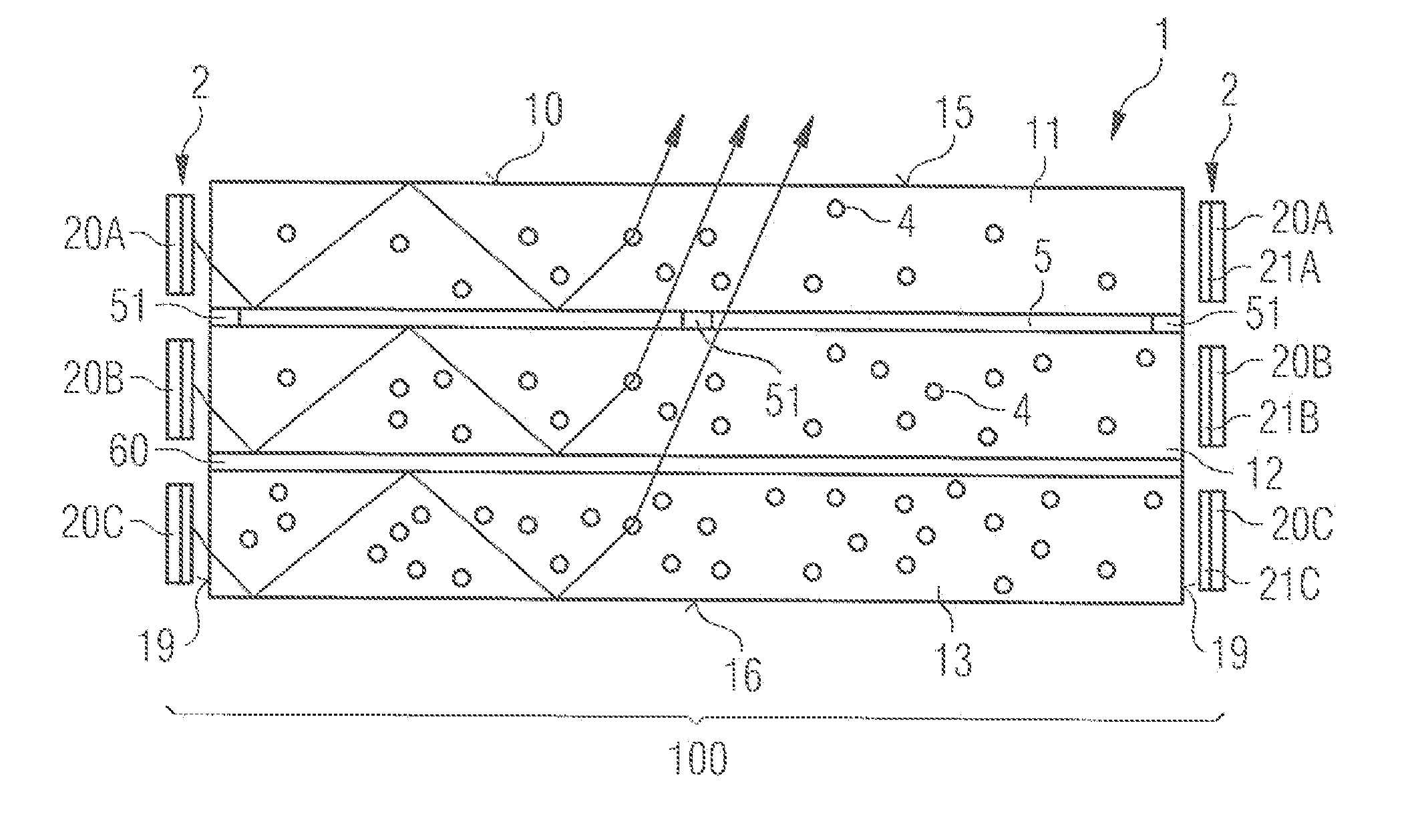
[0060]FIG. 1 shows a planar emitter 100 comprising a surface light guide 1. The surface light guide comprises a first layer 11, a second layer 12 and a further layer 13. The layers 11, 12, 13 are formed between a first interface 15 and a second interface 16. In a vertical direction, that is to say perpendicular to a main extension plane of the surface light guide 1, the interfaces delimit the region of the surface light guide in which the coupled-in radiation propagates, in particular on account of total internal reflection. Scattering locations 4 are formed in the layers 11, 12, 13, and are provided for scattering radiation coupled into the surface light guide laterally, that is to say along a main extension direction of the surface light guide. The proportion of radiation which emerges from a radiation exit area 10 is increased by means of the scattering locations 4.

[0061]The layers 11, 12, 13 are decoupled from one another with regard to the light guidance at least in regions. Th...


PUM


Abstract

A surface light guide has a radiation exit area extending along a main extension plane of the surface light guide and is provided for laterally coupling radiation. The surface light guide includes scattering locations for scattering the coupled radiation. The surface light guide includes a first boundary surface and a second boundary surface which delimit the light conductance of the coupled-in radiation in the vertical direction. A first layer and a second layer are formed on each other in the vertical direction between the first boundary surface and the second boundary surface. Further disclosed are a planar emitter including at least one surface light guide.

Description

[0001]This patent application is a national phase filing under section 371 of PCT / EP2011 / 054454, filed Mar. 23, 2011, which claims the priority of German patent application 10 2010 018 033.5, filed Apr. 23, 2010, each of which is incorporated herein by reference in its entirety.TECHNICAL FIELD[0002]The present patent application relates to a surface light guide and to a planar emitter comprising at least one such surface light guide.BACKGROUND[0003]In conventional radiation sources, the generated radiation typically emerges from a comparatively small area. This area can be enlarged for example by a diffusing screen being disposed downstream. However, this can result in a luminance distribution that is comparatively inhomogeneous over the radiation exit area.SUMMARY OF THE INVENTION[0004]In one aspect, large-area emission can be achieved with high homogeneity.[0005]In one embodiment, a surface light guide comprises a radiation exit area running along a main extension plane of the sur...

Claims


Application Information

Patent Timeline
Patent Type & Authority Applications(United States)
IPC IPC(8): F21V8/00
CPCG02B6/0035G02B6/0041G02B6/0016G02B6/0073G02B6/0076G02B6/0068G02B6/00
Inventor BRICK, PETERKAISER, STEPHANKUHN, GERHARDMARKYTAN, ALESMUSCHAWECK, JULIUSNEUGIRG, CHRISTIAN
Owner OSRAM OPTO SEMICONDUCTORS GMBH & CO OHG
Why Eureka
Try Eureka