Vacuum pump

a vacuum pump and vacuum technology, applied in the field of vacuum pumps, can solve the problems of limited revolution speed of vacuum pump, damage, and fibers in the vicinity of the surface layer of the cylindrical rotor, and achieve the effect of high marketability

Active Publication Date: 2013-05-09
EDWARDS JAPAN
View PDF2 Cites 2 Cited by
  • Summary
  • Abstract
  • Description
  • Claims
  • Application Information

AI Technical Summary

Benefits of technology

[0037]In the invention of claim 8, evacuation performance is little affected also upon widening of the clearance with respect to a fixed section when pressure is low; also, the joining portion is provided upstream of the exhaust passage. As a result, high marketability can be preserved even in case of poor finishing precision of the outer peripheral face of the joining portion.

Problems solved by technology

Thus, the raise of vacuum pump revolution speed is limited by the strength of the rotor at the cylindrical thread groove pump section.
However, the meandering fibers in the vicinity of the surface layer of the cylindrical rotor are shredded during this finish processing.
When acted upon by a high load, therefore, the fibers in the FRP material may partially peel off, become frayed and / or distorted, and be damaged as a result.
The structure disclosed in Japanese Patent Publication No. 3098139, wherein the rotor in the turbo-molecular pump section and the cylindrical rotor in the thread groove pump section are joined to each other by way of a support plate of a FRP material, as a measure against the occurrence of fiber fraying and distortion and resulting damage of fibers, in a cylindrical rotor that is obtained by shaping a conventional FRP material to a cylindrical shape, as described above, is problematic structure on account of the increased number of parts and greater assembly man-hours that such a structure involves.
In some instances, moreover, assembly is difficult to achieve with good precision, and the clearance with respect to a fixed section must be widened in order to prevent contact with the fixed section.
This entails lower evacuation performance, which is likewise problematic.
In a structure as disclosed in Japanese Patent Application Publication No. 2004-278512, i.e., a structure in which the winding angle of fibers of an FRP material, and shaping shapes and conditions, such as resin content, are variously designed, the shape of the FRP material is complex, which is problematic in terms of poorer productivity and higher costs.

Method used


Image

  • Vacuum pump
  • Vacuum pump
  • Vacuum pump

Examples


embodiments

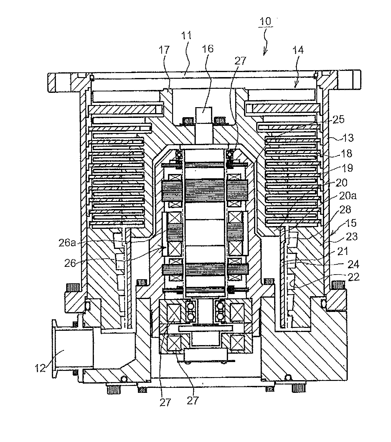
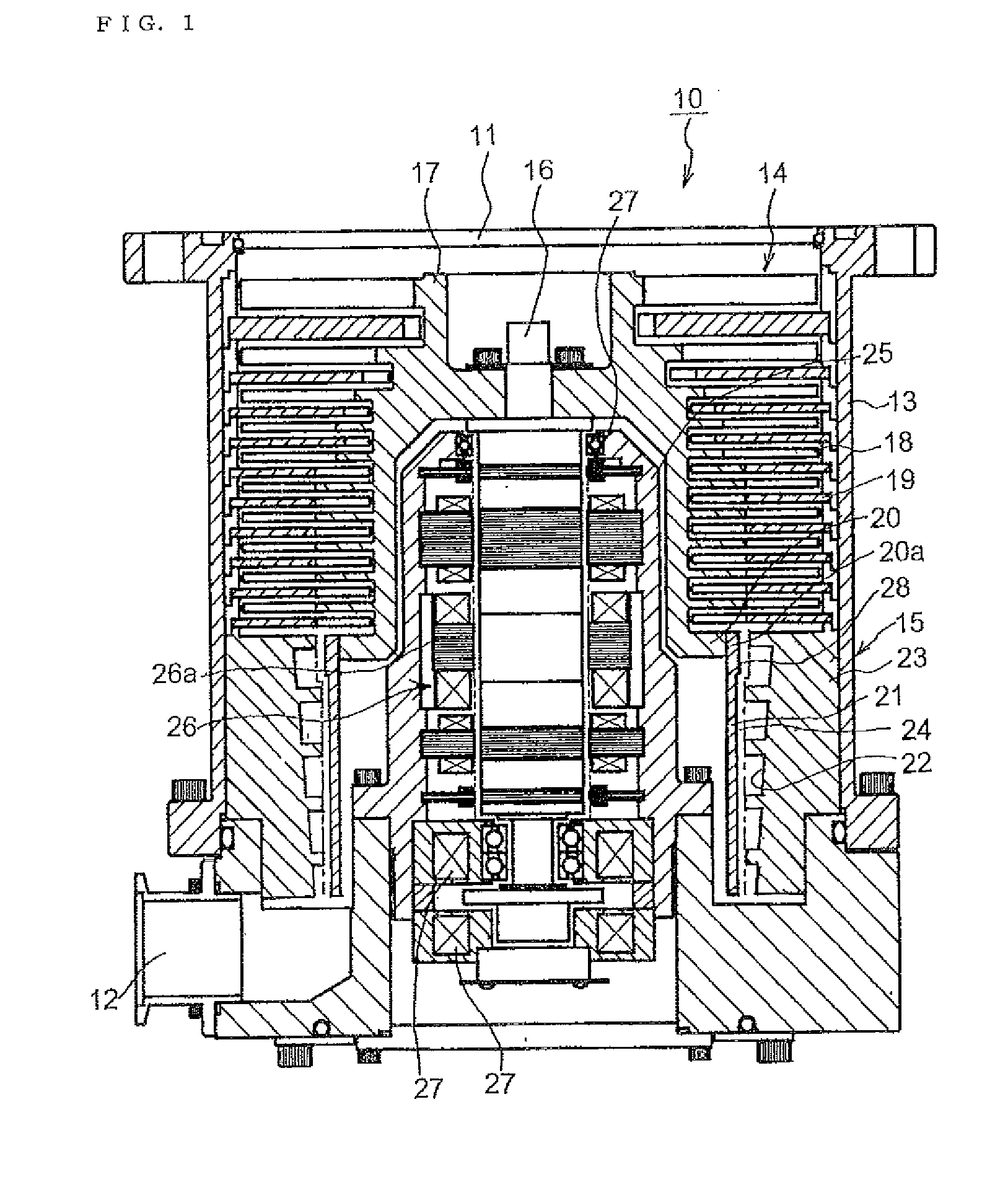
[0042]Preferred embodiments of the vacuum pump of the present invention are explained below with reference to FIG. 1 to FIG. 3. FIG. 1 is a vertical cross-sectional diagram of a vacuum pump according to the present invention.

[0043]In FIG. 1, a vacuum pump 10 comprises a chassis 13 that has an intake port 11 and an exhaust port 12. Inside the chassis 13 there is provided a turbo-molecular pump section 14 at the top, and a cylindrical thread groove pump section 15 below the turbo-molecular pump section 14; and there is formed an exhaust passage 24 that passes through the interior of the turbo-molecular pump section 14 and the thread groove pump section 15 and that communicates the intake port 11 with the exhaust port 12.

[0044]More specifically, the exhaust passage 24 elicits communication between a gap formed between the inner peripheral face of the chassis 13 and the outer peripheral face of a below-described rotor 17 that opposes the turbo-molecular pump section 14, and a gap betwee...


PUM

PropertyMeasurementUnit
angleaaaaaaaaaa
winding angleaaaaaaaaaa
cylindrical shapeaaaaaaaaaa

Abstract

Provided is a vacuum pump in which no finish processing has to be carried out after shaping of a cylindrical rotor even in use of a cylindrical rotor obtained by shaping a fiber-reinforced plastic material into a cylindrical shape. The vacuum pump has a turbo-molecular pump section and a thread groove pump section. The upper end section of a cylindrical rotor, which is obtained by shaping a fiber-reinforced plastic material into a cylindrical shape, of the thread groove pump section, is joined to the lower end section of a rotor of the turbo-molecular pump section. A joining portion of the rotor of the turbo-molecular pump section and the cylindrical rotor of the thread groove pump section is disposed upstream of an exhaust passage. As a result, finish processing does not have to be carried out after shaping of the cylindrical rotor. If finish processing is performed after shaping of the cylindrical rotor a resin may be coated onto a rugged portion of the cylindrical rotor, or fibers may be helically wound at a winding angle not greater than 45 degrees.

Description

BACKGROUND OF THE INVENTION[0001]1. Field of the Invention[0002]The present invention relates to a vacuum pump, and more particularly to a vacuum pump that can be used in a pressure range from medium vacuum to high vacuum and ultra-high vacuum, in an industrial vacuum system used in semiconductor manufacturing, high-energy physics and the like.[0003]2. Description of the Related Art[0004]Conventional vacuum pumps of this type have a structure wherein a turbo-molecular pump section and a cylindrical thread groove pump section are sequentially disposed inside a chassis that has an intake port and an exhaust port.[0005]The rotor or stator at the cylindrical thread groove pump section is made of an aluminum alloy. Thus, the raise of vacuum pump revolution speed is limited by the strength of the rotor at the cylindrical thread groove pump section.[0006]Such being the case, a cylindrical rotor that results from shaping, to a cylindrical shape, a fiber-reinforced plastic material (fiber-re...

Claims


Application Information

Patent Timeline
Patent Type & Authority Applications(United States)
IPC IPC(8): F01D5/02
CPCF04D19/044F04D19/042F01D5/02F04D29/023F04D17/168F05D2230/14F05D2230/18F05D2230/90F05D2260/37F05D2300/121F05D2300/43F05D2300/516F05D2300/603F05D2300/6034F04D19/04F04D25/16F04D29/02
Inventor KABASAWA, TAKASHI
Owner EDWARDS JAPAN
Why Eureka
Try Eureka