Straight intramedullary fracture fixation devices and methods

a fixation device and intramedullary technology, applied in the field of devices, tools and methods for providing bone reconstruction and reinforcement, can solve the problems of multiple traumas and resultant fractures, large number of non-life-threatening fractures, and significant bone fractures

Active Publication Date: 2013-05-09
ARTHREX
View PDF2 Cites 84 Cited by
  • Summary
  • Abstract
  • Description
  • Claims
  • Application Information

AI Technical Summary

Benefits of technology

[0038]In some embodiments, to aid in insertion into the intramedullary canal, at least one component of the fracture fixation device has a substantially flexible state and a substantially rigid state. Once in place, deployment of the device also causes the components to change from the flexible state to a rigid state to aid in proper fixation of the fracture. In some embodiments, at least one of the components may be substantially rigid or semi-flexible. In some embodiments, at least o

Problems solved by technology

Lastly, the acceptance and ubiquitous application of passive restraint systems, airbags, in automobiles has created greater numbers of non-life threatening fractures.
In the past, a person that might expire from a serious automobile accident, now survives with multiple traumas and resultant fractures.
However, with an increasingly aging population, osteoporosis has become more of a significant medical concern in part due to the risk of osteoporotic fractures.
Also, sports and work-related accidents account for a significant number of bone fractures seen in emergency rooms among all age groups.
This can take several months for the bone to heal and for the patient to remove the cast before resuming normal activities.
Invariably, this line of sight access violates, disrupts, and caus

Method used


Image

  • Straight intramedullary fracture fixation devices and methods
  • Straight intramedullary fracture fixation devices and methods
  • Straight intramedullary fracture fixation devices and methods

Examples


first embodiment

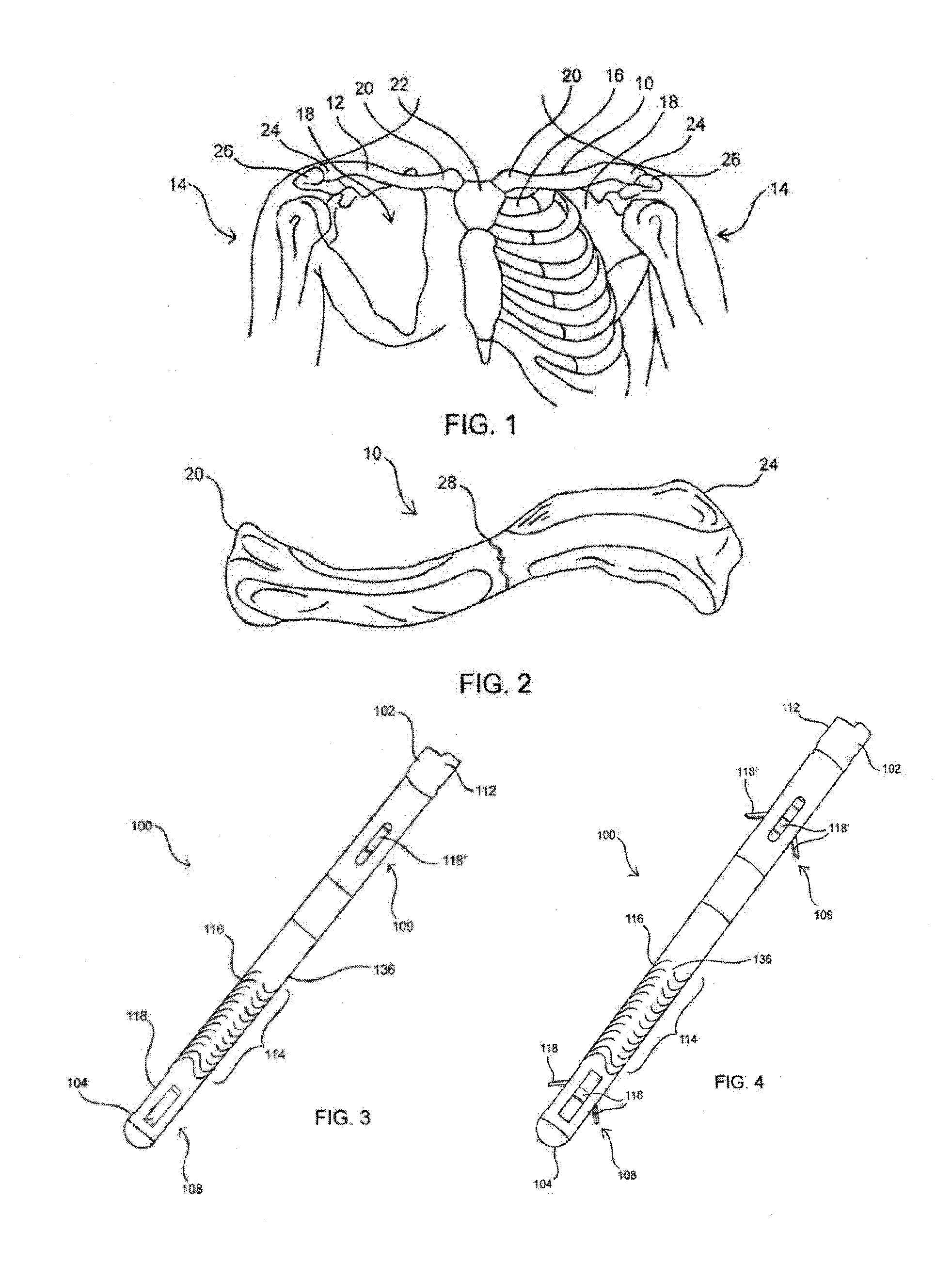
[0250]In a first embodiment, to implant bone fixation device 100 in clavicle 12, an incision is first made at the fracture 28, and tissue is retracted if needed to access the fracture. Fracture 28 is then distracted to gain access to the medial end of the lateral portion of the bone. A channel may then be drilled axially through the lateral portion of the bone from fracture site 28 outward toward the lateral end 24 until it surfaces at the lateral end as shown. A guidewire, such as a K-wire, may first be driven anterior to posterior thereby tenting the posterior skin and the drill guided over the guidewire anterior to posterior in the lateral clavicle segment.

[0251]A second incision may be made where the channel exits lateral end 24 of clavicle 12 in order to access the exit point. A guide wire may then be placed through the second incision and into the lateral exit point of the channel created in the lateral portion of clavicle 12. The guide wire may then be fed medially through th...

second embodiment

[0254]In a second embodiment, to implant bone fixation device 100 in clavicle 12, an incision is first made at the fracture 28. The patient may be positioned in the “beach chair” position or any other suitable position for surgery. The incision is made at the front (anterior side) of the patient adjacent to the fracture. Tissue is retracted if needed to access the fracture and the fracture 28 may then be distracted or elevated to gain access to each of the segments of the bone. The medial segment and lateral segment are then both prepared for the insertion of the device by creating a channel within them.

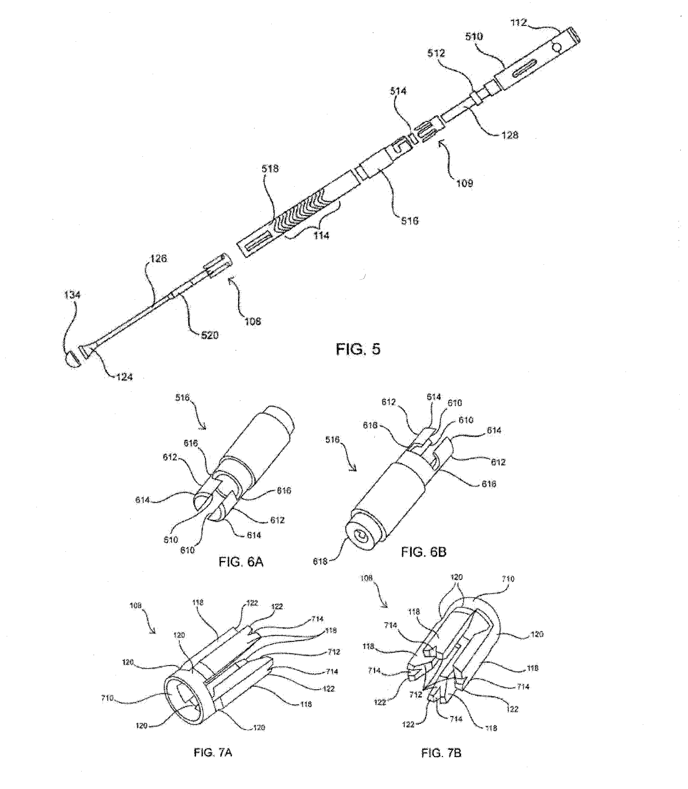
[0255]Any suitable combination of tools may be used to create the channels in both the medial segment and the lateral segment of the clavicle. The tools may include hand tools or power tools. The tools may also include awls, drill bits, guidewires, or any other suitable tools to create a channel within bone. The awls may be curved awls, straight awls, and / or malleable awls (i.e. the ...


PUM


Abstract

A straight intramedullary bone fracture fixation device is provided with an elongate body having a longitudinal axis for deployment in a long bone, such as a clavicle. Methods of repairing a fracture of a bone are also disclosed. One such method comprises inserting a bone fixation device into an intramedullary space of the bone to place at least a portion of an elongate body of the fixation device on one side of the fracture and at least a portion of a hub on another side of the fracture, and engaging an inner surface of the intramedullary space to anchor the fixation device to the bone. Various configurations and designs may be used in combination with other fixation device components.

Description

CROSS-REFERENCE TO RELATED APPLICATIONS[0001]This application claims the benefit of priority of U.S. Provisional Application 61 / 553,059, titled “STRAIGHT INTRAMEDULLARY FRACTURE FIXATION DEVICES AND METHODS”, filed Oct. 28, 2011, which is incorporated by reference in its entirety herein.[0002]This application is a Continuation-in-Part of U.S. application Ser. No. 12 / 482,388, filed Jun. 10, 2009, which claims the benefit of priority of U.S. Provisional Applications: No. 61 / 060,440, filed Jun. 10, 2008; No. 61 / 060,445, filed Jun. 10, 2008; No. 61 / 060,450, filed Jun. 10, 2008; No. 61 / 100,635, filed Sep. 26, 2008; No. 61 / 100,652, filed Sep. 26, 2008; No. 61 / 117,901, filed Nov. 25, 2008; No. 61 / 122,563, filed Dec. 15, 2008; and No. 61 / 138,920, filed Dec. 18, 2008. U.S. application Ser. No. 12 / 482,388 is also a Continuation-in-Part of U.S. application Ser. No. 11 / 383,269, filed May 15, 2006 which claims the benefit of priority of U.S. Provisional Application No. 60 / 682,652, filed May 18, ...

Claims


Application Information

Patent Timeline
IPC IPC(8): A61B17/72
CPCA61B17/7233A61B17/1725A61B17/7208A61B2019/301A61B17/7266A61B2090/031
Inventor NELSON, CHARLES L.MCDANIEL, STEPHEN R.HARTDEGEN, JR., VERNON R.PHAM, TRUNG HOFLETCHER, DARRYLL LEONARD CHARLESBROWN, NATHAN D.
Owner ARTHREX
Why Eureka
Try Eureka