
Fluid cooled showerhead with post injection mixing

a technology of flue gas injection and showerhead, which is applied in the direction of manufacturing tools, coatings, metal working devices, etc., can solve the problems of increasing the cost of showerheads, complex manufacturing, and manufacturing costs, and achieves fewer parts, improved manufacturing efficiency, and improved reliability

Inactive Publication Date: 2013-05-16
ADVANCED MICRO-FABRICATION EQUIP INC ASIA
View PDF5 Cites 180 Cited by
  • Summary
  • Abstract
  • Description
  • Claims
  • Application Information

AI Technical Summary

Benefits of technology

The invention provides a showerhead that can be used in various processing chambers, especially in applications where separate gas delivery and active cooling are required. This showerhead is simplified in fabrication, has fewer parts, is more robust, and is cheaper to manufacture.

Problems solved by technology

One problem of the prior art designs is the complexity and cost of manufacturing.
This leads to intricate designs that increase the cost of the showerhead.

Method used


Image

  • Fluid cooled showerhead with post injection mixing
  • Fluid cooled showerhead with post injection mixing
  • Fluid cooled showerhead with post injection mixing

Examples


Embodiment Construction

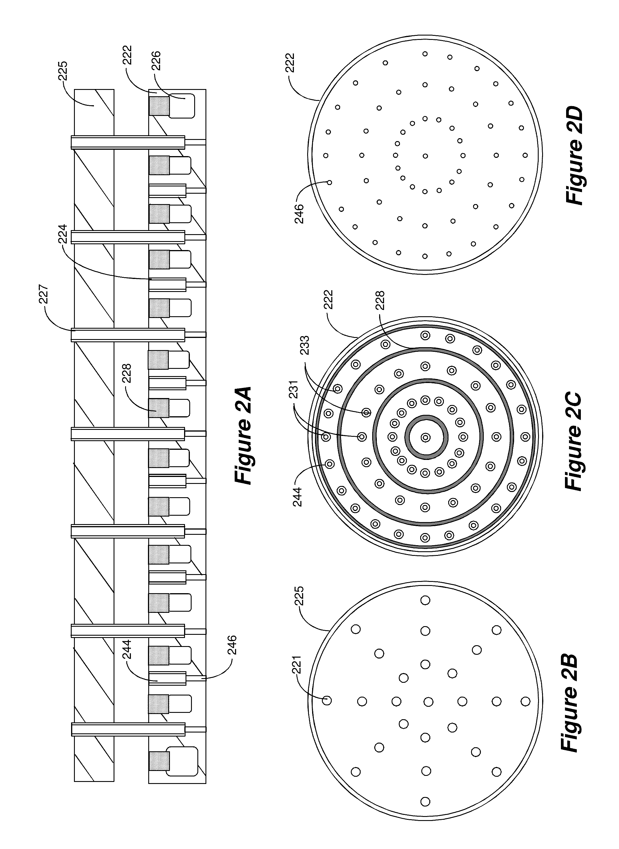
[0019]Embodiments of the invention provide showerhead designs that are simpler to manufacture, require fewer parts, and are of lower cost. In general, various embodiments of the invention provide a showerhead made of only two plates, yet capable of separate injection of processing gas and liquid cooling of the lower plate.

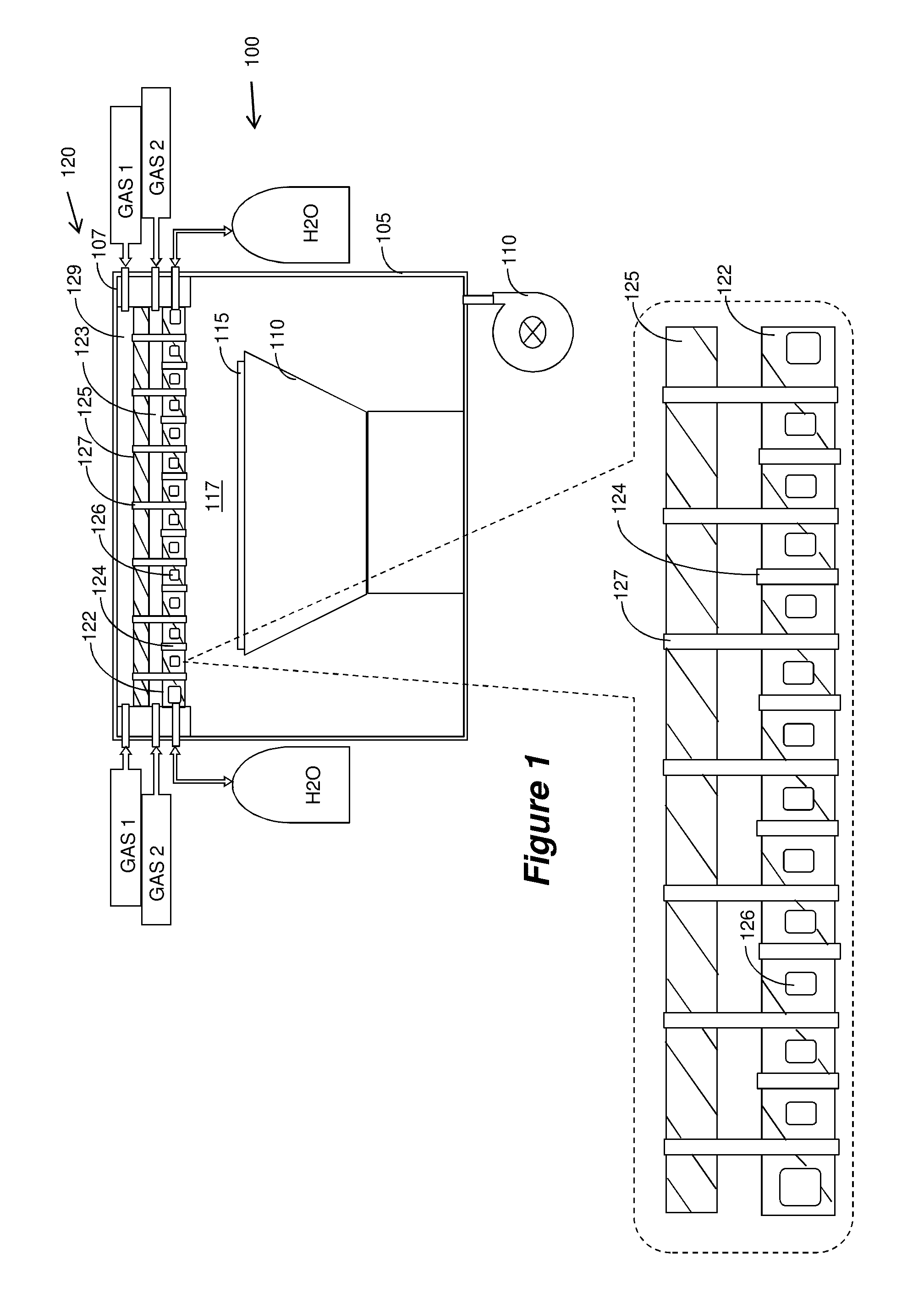
[0020]FIG. 1 illustrates an example of a processing chamber 100 utilizing a showerhead, generally indicated at 120, fabricated in accordance with embodiments of the invention. FIG. 1 illustrates the general structure of showerhead 120, while more detailed examples are provided in other Figures. In FIG. 1, chamber 100 includes an enclosure 105 that is evacuated by vacuum pump 110. A pedestal 11 supports one or more substrates 115 to be processed. The showerhead 120 is used to inject process gas 1 and process gas 2 into the chamber. The process gasses are kept separately until injection into the chamber, wherein they mix and react so as to provide the necessary proce...


PUM

PropertyMeasurementUnit
Thicknessaaaaaaaaaa
Diameteraaaaaaaaaa

Abstract

A showerhead that injects two process gases into the processing chamber via separate sets of holes. The showerhead is constructed of upper plate and lower plate. Upper plate has a first set of holes. The lower plate has two sets of holes: one set is aligned with the holes in the upper plate, while the second set has no corresponding holes in the upper plate. Both sets of holes in the lower plate are made to have two different diameters: a larger diameter extending from the top surface of the lower plate, while a smaller diameter extends from the bottom surface and meets with the larger diameter. A set of pipes are inserted through the holes in the upper plate and the corresponding holes in the lower plate, and are sealingly brazed to both plates. Cooling channels may be provided in the lower plate.

Description

RELATED APPLICATION[0001]This application claims priority from Chinese Patent Application Serial No. 201110355292.7, which was filed on Nov. 10, 2011, the entire disclosure of which is incorporated herein by reference.BACKGROUND[0002]1. Field of the Application[0003]This application is in the field of gas injection into processing chambers, especially for applications requiring showerheads with active cooling and post-injection mixing.[0004]2. Related Art[0005]Various processing chambers are known in the art and are used for fabrication of semiconductor devices, flat panels, solar cells, etc. An example of such chambers include chemical vapor deposition (CVD), plasma enhanced chemical vapor deposition (PECVD), metal organic chemical vapor deposition (MOCVD), vapor phase epitaxy (VPE), etc. In various applications, it is required that the processing gases will not mix prior to injection into the processing chambers. Accordingly, various designs have been proposed for showerheads that...

Claims


Application Information

Patent Timeline
IPC IPC(8): C23C16/455B23P17/04B05B7/08
CPCC23C16/4409C23C16/45565Y10T29/49826C23C16/45574C23C16/45572
Inventor HO, HENRYJIANG, YONG
Owner ADVANCED MICRO-FABRICATION EQUIP INC ASIA
Learn More