
Device for subjecting a fluid to a disinfecting treatment by exposing the fluid to ultraviolet light

a technology of disinfecting treatment and fluid, which is applied in the direction of material analysis using wave/particle radiation, instruments, chemistry apparatus and processes, etc., can solve the problems of reducing the intensity of ultraviolet light, limiting throughput, and limited penetration depth of ultraviolet light into the fluid, so as to achieve the effect of enhancing electrical conductivity

Inactive Publication Date: 2013-05-16
SIGNIFY HLDG BV
View PDF7 Cites 12 Cited by
  • Summary
  • Abstract
  • Description
  • Claims
  • Application Information

AI Technical Summary

Benefits of technology

The present invention provides a device for compensating for the decrease in ultraviolet intensity with distance in a reactor. The device includes means for locally enhancing the electrical conductivity in a space between the reactor wall and the light emission means. This can be achieved by using electrically conductive material, such as a plate with holes or a closed central portion, to reduce the electrical resistance at positions where the ultraviolet intensity is reduced. The means for enhancing conductivity can also reflect ultraviolet light and shield parts of the device from ultraviolet radiation during operation. The device can have a compact design with a minimum number of parts. Overall, the invention allows for a more evenly distributed ultraviolet output and increases the disinfecting capacity of the reactor.

Problems solved by technology

Especially if the fluid to be treated has a low transmittance, the penetration depth of the ultraviolet light into the fluid is limited.
The reduction of the intensity of the ultraviolet light with distance either limits throughput in the devices having the ultraviolet lamp, or requires a minimal volume of the space in which the lamp is arranged, or requires strong mixing and turbulence, increasing the pressure loss over the space.
However, this solution has some disadvantages, including a reduced lifetime of the lamp.

Method used


Image

  • Device for subjecting a fluid to a disinfecting treatment by exposing the fluid to ultraviolet light
  • Device for subjecting a fluid to a disinfecting treatment by exposing the fluid to ultraviolet light
  • Device for subjecting a fluid to a disinfecting treatment by exposing the fluid to ultraviolet light

Examples


Embodiment Construction

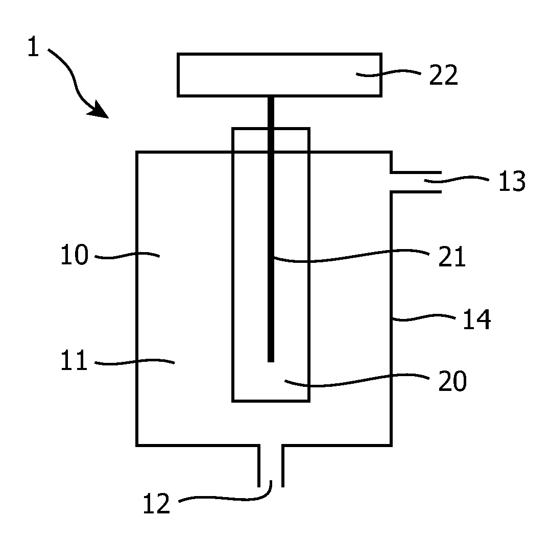
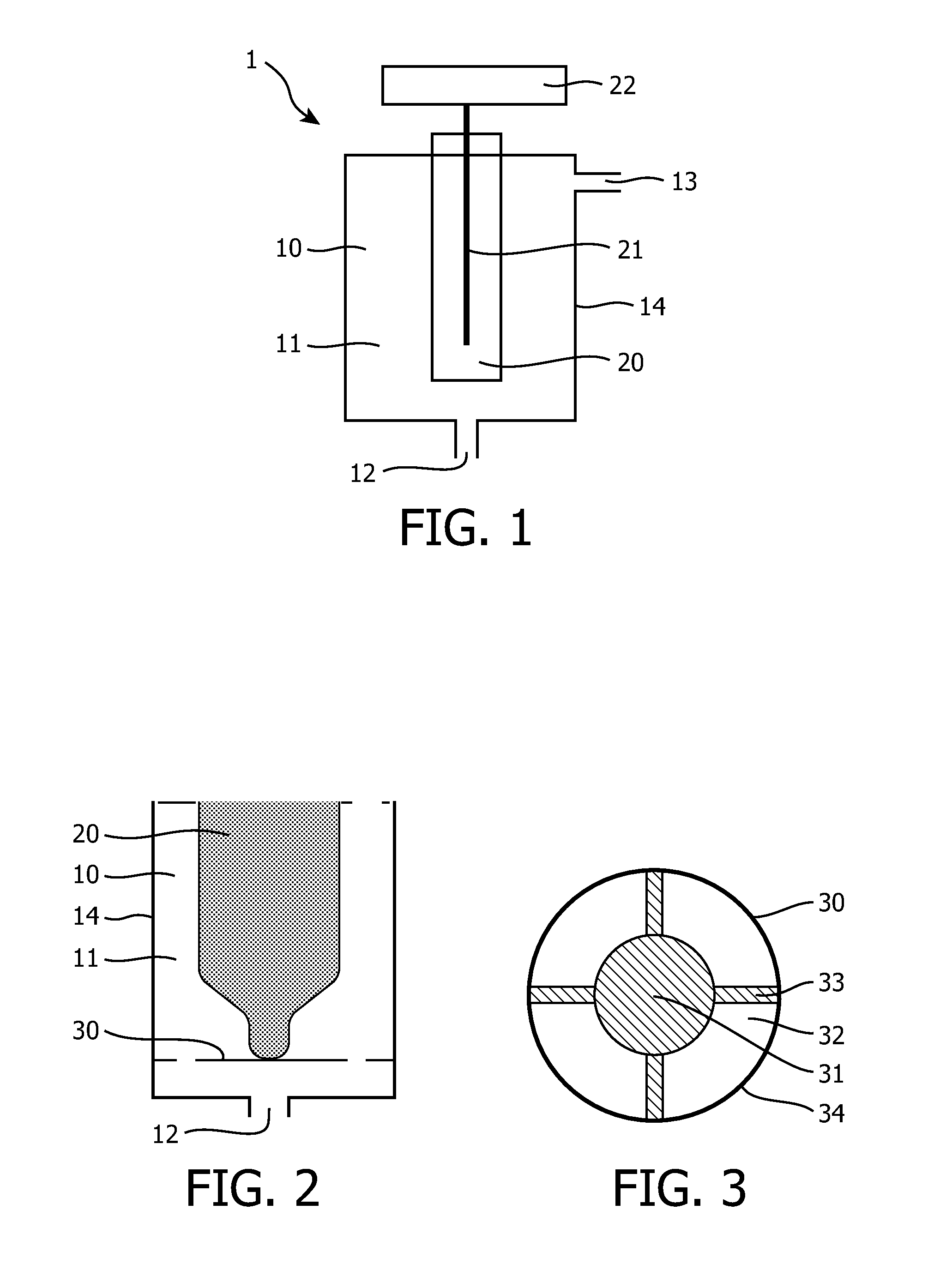
[0023]FIG. 1 shows a device 1 which is designed to be used for disinfecting water.

[0024]For the sake of completeness, it is noted that this device 1 is described as one example of many devices which are feasible within the scope of the present invention, including air purification devices and devices for disinfecting liquids other than water.

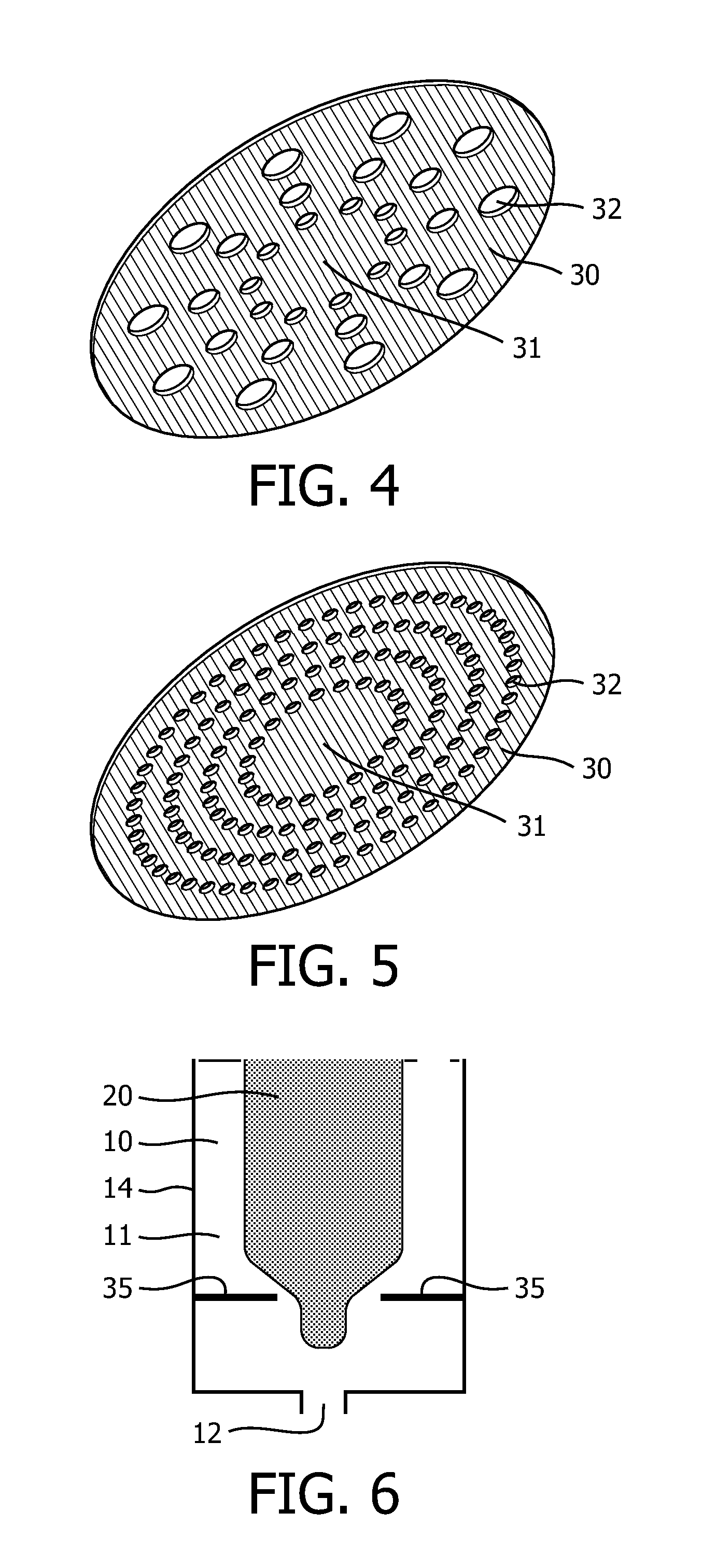
[0025]The water disinfecting device 1 comprises a reactor 10, i.e. a container having an inner space 11 in which the water disinfecting process is meant to take place during operation of the device 1. The reactor 10 has an inlet 12 for letting in water to be treated, and an outlet 13 for letting out water. Furthermore, the water disinfecting device 1 comprises a lamp 20 for emitting ultraviolet light, which lamp is arranged inside the reactor 10. In the shown example, the lamp 20 has an elongated shape, and has a central position in the reactor 10, which is the most practical position, since this allows effective use of the entire surface of the...


PUM


Abstract

A device for subjecting a fluid to a disinfecting treatment by exposing the fluid to ultraviolet light comprises a reactor (10) having an inner space (11) in which means (20) for emitting ultraviolet light are arranged, an inlet (12) for letting fluid into the inner space (11), and an outlet for letting out fluid from the inner space (11). The light emission means (20) comprise a single electrode, wherein a wall (14) encompassing the inner space (11) is adapted to function as an electrode and comprises electrically conductive material, and wherein the device further comprises means (30) which also comprise electrically conductive material, and which are arranged for locally enhancing the electrical conductivity in a space between the reactor wall (14) and the light emission means (20). By applying these means (30), it is achieved that the disinfecting effect of the ultraviolet light treatment can be

Description

FIELD OF THE INVENTION[0001]The present invention relates to a device for subjecting a fluid to a disinfecting treatment by exposing the fluid to ultraviolet light, said device comprising a reactor having an inner space in which means for emitting ultraviolet light are arranged, an inlet for letting fluid into the inner space, and an outlet for letting out fluid from the inner space, wherein the light emission means comprise a single electrode, and wherein a wall encompassing the inner space is adapted to function as an electrode and comprises electrically conductive material.BACKGROUND OF THE INVENTION[0002]A device for subjecting a fluid to a disinfecting treatment by exposing the fluid to ultraviolet (UV) light is well-known. For example, for the microbiological disinfection of drinking water, it is known to use a source / lamp for emitting so-called UV-C radiation, which is ultraviolet light having relatively short waves with a wavelength in the order of 100 to 280 nm. For domesti...

Claims


Application Information

Patent Timeline
IPC IPC(8): A61L2/10
CPCC02F1/325C02F2301/022C02F2201/3228C02F2201/3223
Inventor MONDT, EVAHOLWERDA, EINTEHAYASHI, DAIYUGREUEL, GEORG
Owner SIGNIFY HLDG BV
Learn More